Page 2 of 2
Re: Progress Build of a Holy Grail Model Display-Renwal’s Visible Automobile Chassis and Visible V8 Engine
Posted: Fri Feb 20, 2026 2:29 pm
by Phillip1
Stokesy44-Thanks! I will admit I am not that knowledgeable on car mechanics so I have leaned a lot while building this model. I expect the learning to continue when the V8 engine is built.

Phillip1
Re: Progress Build of a Holy Grail Model Display-Renwal’s Visible Automobile Chassis and Visible V8 Engine
Posted: Thu Feb 26, 2026 10:28 pm
by Phillip1
Re: Progress Build of a Holy Grail Model Display-Renwal’s Visible Automobile Chassis and Visible V8 Engine
Posted: Fri Feb 27, 2026 3:58 am
by digger303
Well done and nicely finished.
Re: Progress Build of a Holy Grail Model Display-Renwal’s Visible Automobile Chassis and Visible V8 Engine
Posted: Fri Feb 27, 2026 3:58 am
by digger303
Re: Progress Build of a Holy Grail Model Display-Renwal’s Visible Automobile Chassis and Visible V8 Engine
Posted: Fri Feb 27, 2026 10:46 am
by Stokesy44
Beautiful work and a great finish.
Re: Progress Build of a Holy Grail Model Display-Renwal’s Visible Automobile Chassis and Visible V8 Engine
Posted: Fri Feb 27, 2026 1:27 pm
by Stokesy44
Re: Progress Build of a Holy Grail Model Display-Renwal’s Visible Automobile Chassis and Visible V8 Engine
Posted: Fri Feb 27, 2026 2:29 pm
by Phillip1
digger303/Stokesy44-Thanks very much for the compliments and support.
Phillip1
Re: Progress Build of a Holy Grail Model Display-Renwal’s Visible Automobile Chassis and Visible V8 Engine
Posted: Thu Mar 12, 2026 1:25 pm
by Phillip1
Fellow Modelers-The second part of this project begins here.
(PART 2-VISIBLE V8 ENGINE)
Renwal’s Visible V8 Engine kit was released in 1960 and became one of the most popular and best-selling plastic models ever produced. It remained in Renwal’s product line catalog every year until the company went out of business, and was re-issued by Revell multiple times after they acquired the molds in 1976. The finished model had an electric motor that powered the crankshaft, pistons, camshaft, rocker arms, push rods, lighted firing sparkplugs, cooling fan, generator fan and fuel pump actuator arm (over 100 moving parts!). In 1994, Revell permanently modified the molds by removing all the electrical components and incorporated a hand-crank assembly to operate the moving parts. Although I have never read why this was done my guess is they wanted to simplify the kit and make it a more “kid friendly” build.
Figure V8001: Here is the box art for the kit I have. This first Revell re-issue was released in 1977 and is nearly identical to the original Renwal offerings. The box size is huge, much larger than it needed to be.

Figure V8001a: This gorgeous box artwork painting was used when the kit was originally issued in 1960. It had everything an advertising company felt made up an idealized America of the early 1960’s including a great view of the built model, an excited short-haired kid, and an all-wise pipe smoking dad peering over the boy’s shoulder ready to lend a hand if needed.

Figures V8001b: According car model experts on the Internet, Renwal’s V8 was not based on any single engine, but shared a lot of similarities with Studebaker’s 1951 V8 shown in this image.

Figure V8001c: Here are the all the parts after being sorted by assembly step. This model has a total of 353 pieces (241 styrene plastic/112 hardware) and is molded in three colors (black/gray/red) and clear. My assumption is the V8 will be easier to build than the chassis because it is smaller and has fewer parts, but cleaning the parts will still be the most time consuming and tedious part of the build.

Figure V8001d: This image shows a detailed breakdown of the hardware parts, which is a lot less hardware than the visible chassis had.

Figures 001e through 001f: Shown are the kit instructions and a 12 page booklet on how a real auto engine works.


Figure V8001g: Step 1 is the assembly of the main frame. I will be using the same strategy on the V8 that was used on the visible chassis, which is to leave the clear and integrated moving parts unpainted.

Figure V8001h: Here are the parts after being cleaned up.

Figure V8001i: The clear braces and hex nuts have been glued in place.

Figure V8002: Step 2 is the assembly of the crankshaft.

Figure V8002a: As expected, just about every part (like the one shown here) had mold lines, injection pin marks and flash that had to be removed. In cleaning up the opaque parts I used all the following sandpaper grits: 400/600/1000/2,000/4,000/6,000/12,000. Doing this meant every part was very smooth and had a slick finish, which ensured the moving parts would move easier and require less lubricant.

Figure V8002b: Here are the parts after being cleaned up.

Figure V8002c: Here is the completed crankshaft. These parts are supposed to have an interference fit with each other but some of the connections were loose and required a small amount of superglue to hold them in place.

Figure V8003: Step 3 is the installation of the crankshaft to the mainframe.

Figure V8003a: Some parts had really large sink holes that had to be filled.

Figure V8003b: Here are the parts after being cleaned up.

Figures V8003c through V8003e: These images show several views after installation of the crankshaft. A very small amount of WD40 Specialist Silicon was applied where the crankshaft attached to the mainframe.


Figure V8004: Step 4 is the assembly and installation of the pistons.

Figure V8004a: The piston locator pins were cut off so a better alignment between the left and right sides could be achieved.

Figure V8004b: Here are the parts after being cleaned up.

Figures V8004c through V8004d: These images show front and rear views after installation of the pistons.


Until next time...
Phillip1
Re: Progress Build of a Holy Grail Model Display-Renwal’s Visible Automobile Chassis and Visible V8 Engine
Posted: Fri Mar 13, 2026 7:12 am
by Stokesy44
Looks like a fantastic kit to work on. The crank shaft looks superb.
I'm learning more about engines and gear boxes from your thread than I ever have! Great work.

Re: Progress Build of a Holy Grail Model Display-Renwal’s Visible Automobile Chassis and Visible V8 Engine
Posted: Fri Mar 13, 2026 2:45 pm
by Phillip1
Stokesy44-Thanks! I am also learning more about car engines and transmissions than I ever have before!
Phillip1
Re: Progress Build of a Holy Grail Model Display-Renwal’s Visible Automobile Chassis and Visible V8 Engine
Posted: Fri Mar 13, 2026 8:22 pm
by RangerNeil
The chassis build was an amazing job - congratulations on that.

The V8 looks like it will be the equal - looking forwards to seeing this finished.
Re: Progress Build of a Holy Grail Model Display-Renwal’s Visible Automobile Chassis and Visible V8 Engine
Posted: Fri Mar 13, 2026 9:38 pm
by Phillip1
Neil-Thanks for the kind words! I appreciate that you are following along.
Phillip1
Re: Progress Build of a Holy Grail Model Display-Renwal’s Visible Automobile Chassis and Visible V8 Engine
Posted: Sat Mar 14, 2026 1:10 pm
by Kevthemodeller
Looks like this is going to be another great build following on from the chassis


Re: Progress Build of a Holy Grail Model Display-Renwal’s Visible Automobile Chassis and Visible V8 Engine
Posted: Sat Mar 14, 2026 9:08 pm
by Phillip1
Kev-Thanks for the compliment and glad to have you here!
Phillip1
Re: Progress Build of a Holy Grail Model Display-Renwal’s Visible Automobile Chassis and Visible V8 Engine
Posted: Fri Mar 20, 2026 1:17 pm
by Phillip1
Fellow Modelers-Here is the next update.
Figure V8005: Step 5 is the assembly and installation of the cylinder details.

Figure V8005a: The clarity of the clear cylinder wall parts was not very impressive but Novus fine scratch remover and plastic polish was applied to make them look as good as possible.

Figure V8005b: One cylinder wall part and cylinder bottom block part are shown after being glued together. One thing I did not like about this model is it required gluing some of the clear parts together (instead of using bolts and nuts), which kind of defeats the purpose of trying to achieve a very clean and neat build.

Figures V8005c through V8005d: Here are images of the overall assembly after the cylinder parts were glued into place.


Figure V8006: Step 6 is the installation of the front and rear block walls.

Figure V8006a: Here the rear block wall is in the process of getting any small scratches removed before being bolted in place.

Figures V8006b through V8006c: Here are front and rear views after the block walls were added. Warping on some of the clear parts really made fitting them together a frustrating nightmare!


Figure V8007: Step 7 is the assembly and installation of the camshaft.

Figures V8007a through V8007b: Here are the parts after being cleaned up.


Figure V8007c: After the camshaft was installed, the “timing marks” on the large and small gears were lined up so the movement of the pistons and rocker arms would be in sync like on an actual car.

Figure V8007d: The connection between the two gear’s teeth was not tight and slipped some during rotation. To eliminate this, I made a small spacer out of very thin Evergreen styrene and added it at the top of the camshaft opening. It is seen as a white rectangle in this closeup photo.

Figure V8007e: Here is an upside down view of the assembly at this point in the build.

Figures V8008b through V8013: Steps 8, 9, 10, 12 and 13 were skipped because either the parts were not needed or these same parts had already been built on the chassis model.
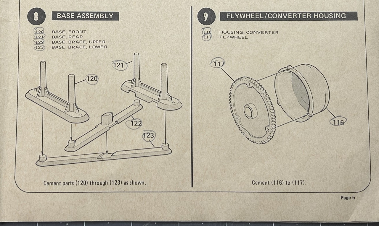
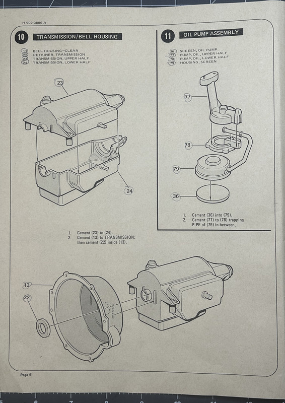
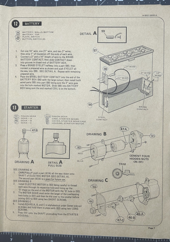
Figure V8014: Step 14 is the assembly and installation of the oil pump and pan.

Figure V8014a: Here are the parts for Step 11 and Step 14 after being cleaned up.

Figure V8014b: The oil pump assembly in this image is the first item I painted on the V8 engine.

Figure V8014c: The oil pump is shown after being fastened in place.

Figure V8014d: The oil pan is shown after being snapped in place.

Figures V8015 through V8016: Steps 15 and 16 connect the engine assembly to the chassis clutch/transmission.


Figure V8016a: The clutch/transmission was disconnected from the chassis model and bolted to the V8 engine. The assembly was also temporarily connected to the battery/control box to confirm all the moving parts operated smoothly.

Figure V8016c: Having the clutch, transmission and V8 engine all connected also allowed me to do a test fit to confirm they would attach to the chassis without any spacing or alignment issues. This image shows everything fit together just like it was supposed to, which was a big relief!

Until next time...
Phillip1
Re: Progress Build of a Holy Grail Model Display-Renwal’s Visible Automobile Chassis and Visible V8 Engine
Posted: Fri Mar 20, 2026 11:39 pm
by digger303
Re: Progress Build of a Holy Grail Model Display-Renwal’s Visible Automobile Chassis and Visible V8 Engine
Posted: Sat Mar 21, 2026 9:12 am
by Stokesy44
Amazing work, great skills and fascinating subject matter
Re: Progress Build of a Holy Grail Model Display-Renwal’s Visible Automobile Chassis and Visible V8 Engine
Posted: Sat Mar 21, 2026 9:41 pm
by cor
I want to see a quarter size person drive it around.
Re: Progress Build of a Holy Grail Model Display-Renwal’s Visible Automobile Chassis and Visible V8 Engine
Posted: Sat Mar 21, 2026 11:32 pm
by Phillip1
digger303-Thanks! Those are some big popcorn buckets you are holding!
Stokesy44-Thank you very much!
cor-I would buy tickets to see that myself!
Phillip1
Re: Progress Build of a Holy Grail Model Display-Renwal’s Visible Automobile Chassis and Visible V8 Engine
Posted: Sun Mar 22, 2026 9:50 am
by digger303
Phillip1 wrote: Sat Mar 21, 2026 11:32 pm
digger303-Thanks! Those are some big popcorn buckets you are holding!
Stokesy44-Thank you very much!
cor-I would buy tickets to see that myself!
Phillip1
Necessary when watching a big project come together

Re: Progress Build of a Holy Grail Model Display-Renwal’s Visible Automobile Chassis and Visible V8 Engine
Posted: Fri Mar 27, 2026 5:14 pm
by Phillip1
Fellow Modelers-Here is the next update.
Figure V8017: Step 17 is the assembly of the exhaust and intake manifolds.

Figures V8017a through V8017c: These images show the exhaust manifold parts out of the box, after the HORRIBLE seam lines have been removed and after final painting.


Figures V8017d through V8017f: These images show the intake manifold parts out of the box, after the HORRIBLE seam lines have been removed and after final painting.


Figure V8018: Step 18 is the assembly of the carburetor, oil filter and air cleaner housing.

Figures V8018a through V8018c: These images show the carburetor, oil filter and air cleaner housing parts out of the box, after the seam lines have been removed and after final painting.


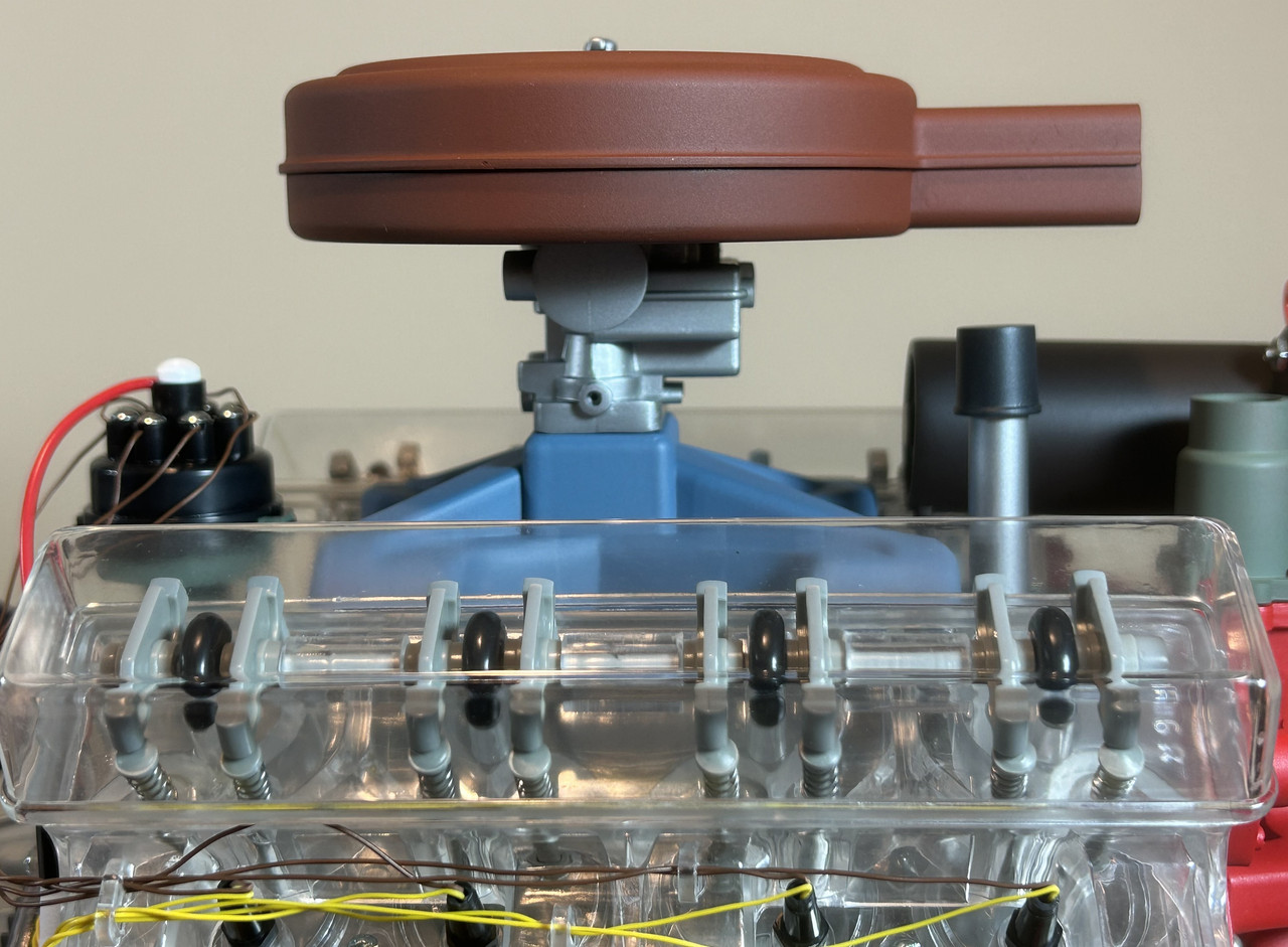
Figure V8018d: This image shows the final stacking of the air cleaner housing, carburetor and intake manifold after being glued together.

Figure 014: Step 19 is the assembly of the cylinder heads.

Figures V8019a through V8019b: Here are the cylinder head clear parts after being cleaned up and then glued together.


Figure V8019c: Here are all the parts after being cleaned up.

Figure V8019d: The rocker arms and rocker arm shafts have been added.

Figure V8019e: The valves, stems and springs are cleaned up and ready to be connected to the rocker arms.

Figures V8019f through V8019g: First the springs and stems were loaded, then the large and small valves were glued to the bottom of the stems. The instructions say to tape down a No. 2 pencil across the top of all the rocker arms to keep the springs loaded on one side, but by using superglue I was able to get all of the parts in place and glued together without having to do this.


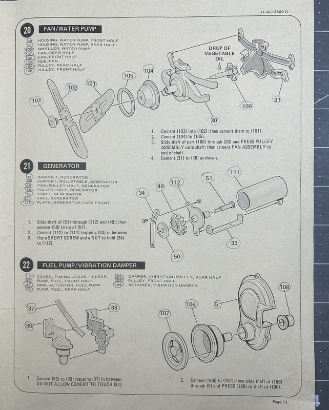
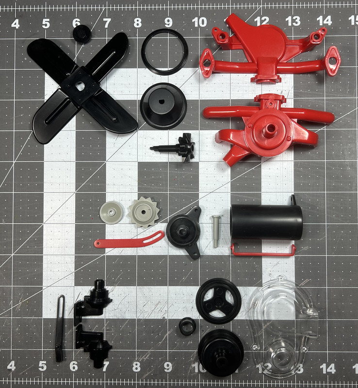
Figures V8020 through 022: Steps 20, 21 and 22 are the assemblies of the cooling fan/water pump, generator, fuel pump and vibration damper.
Figures V8020 through 022a: Here are the separated parts of all four assemblies after being cleaned up.
Figures V8020 through 022d: These images show the cooling fan/water pump after painting and final assembly.
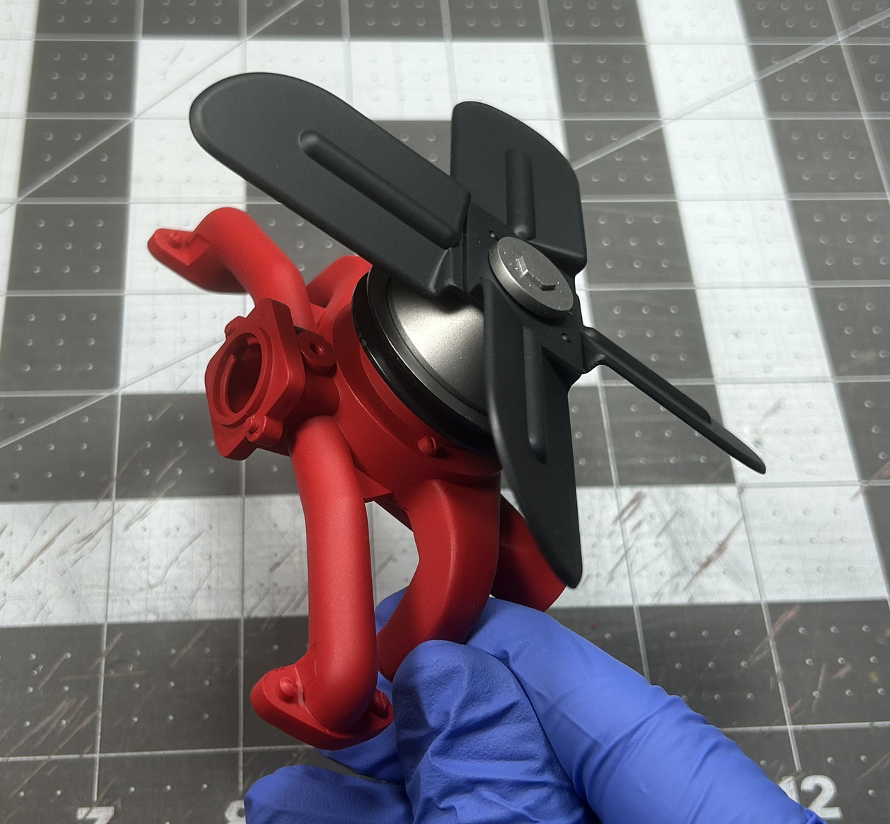
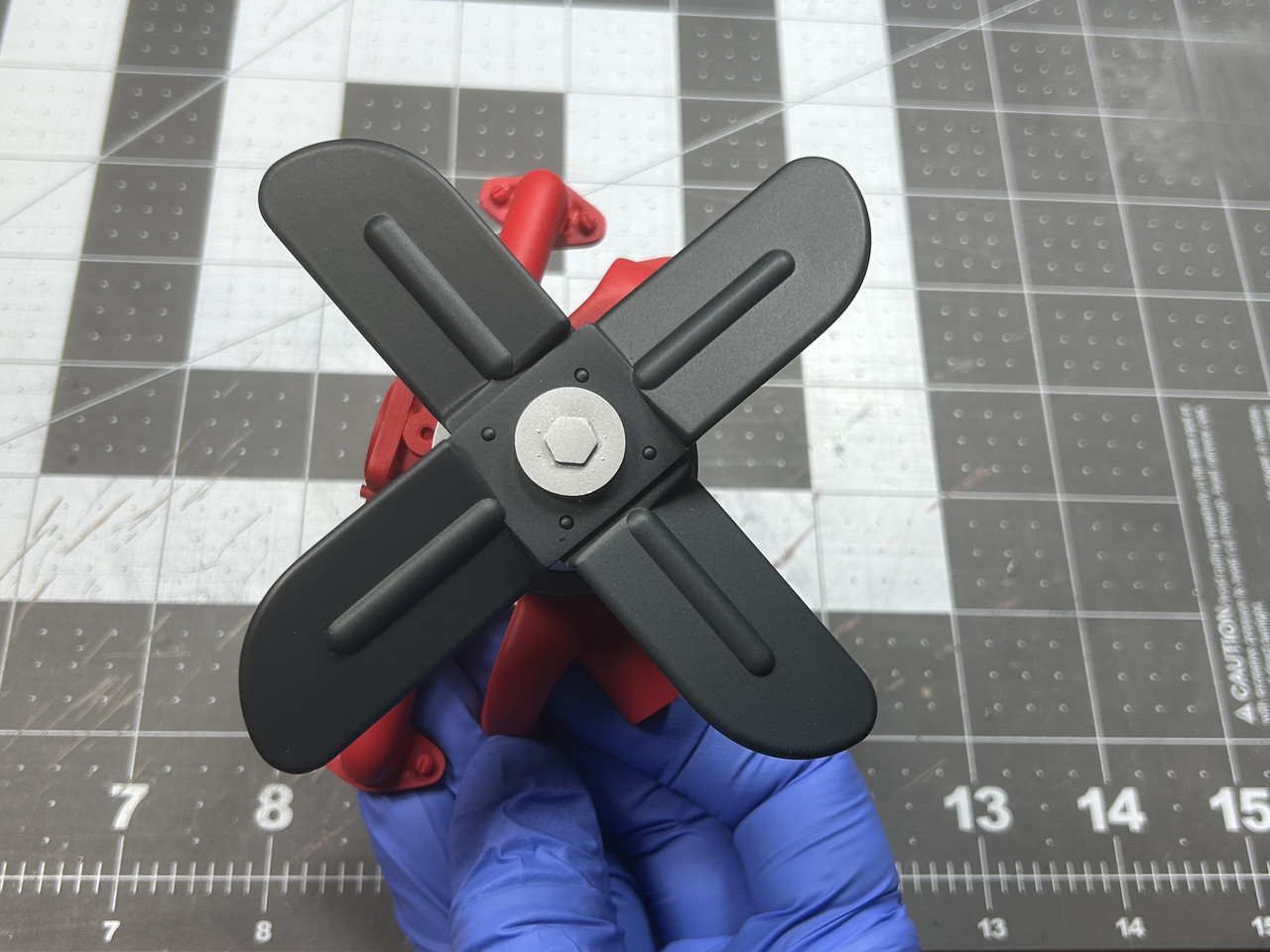
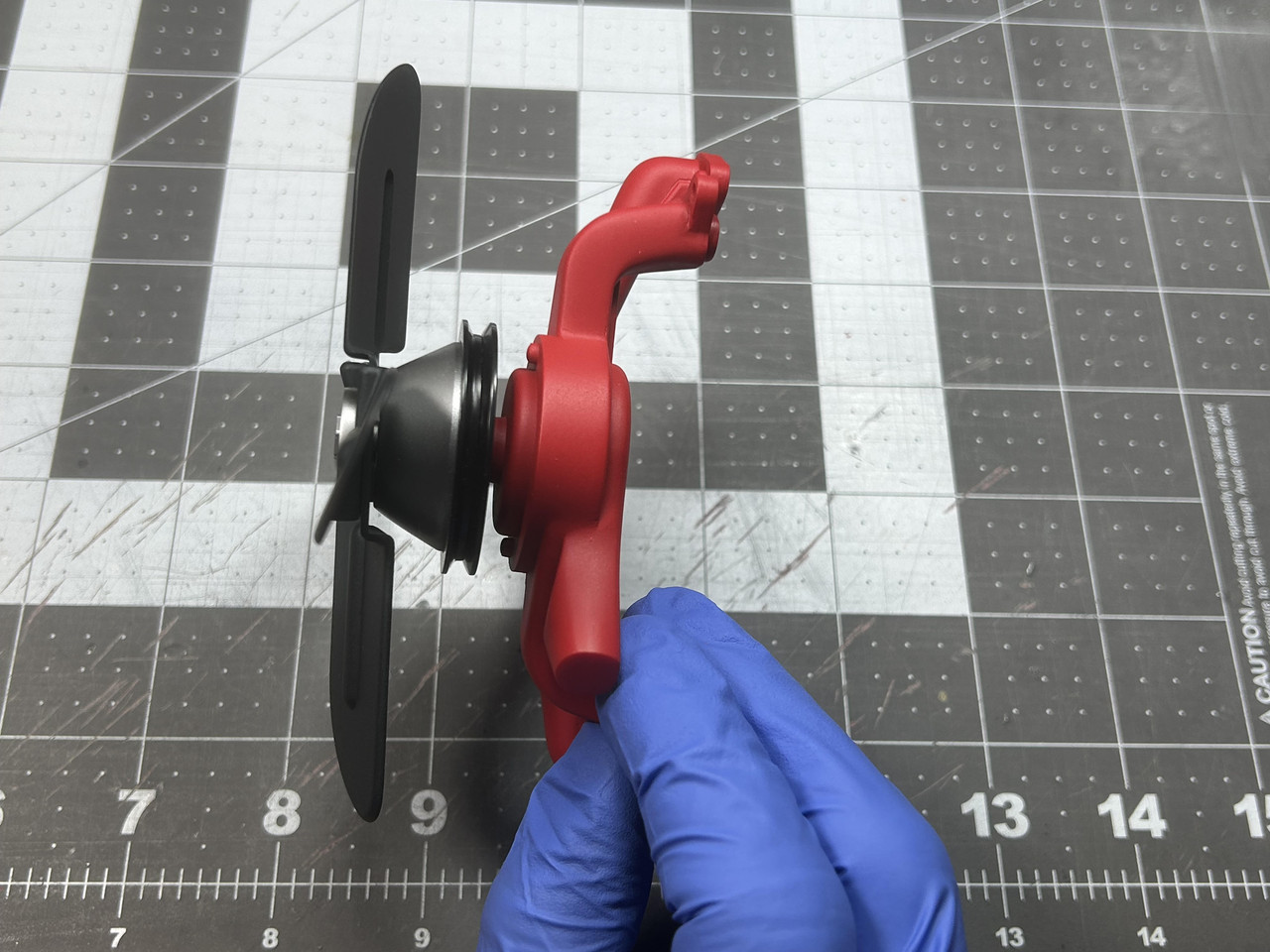
Figure V8020 through 022e: This image shows the generator after painting and final assembly.
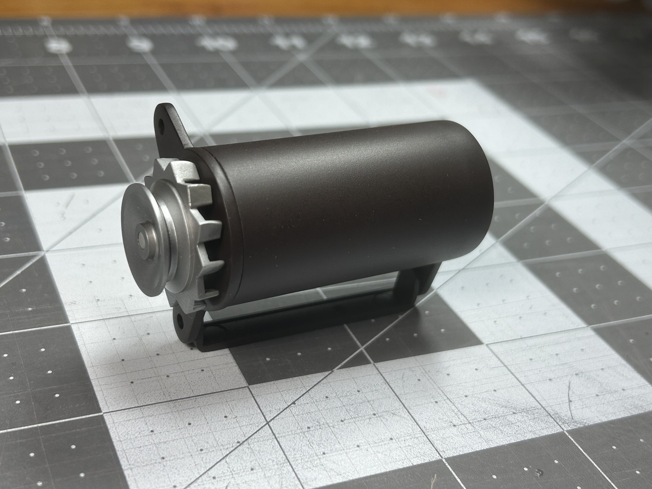
Figure V8020 through 022f: This image shows the fuel pump after painting and final assembly.
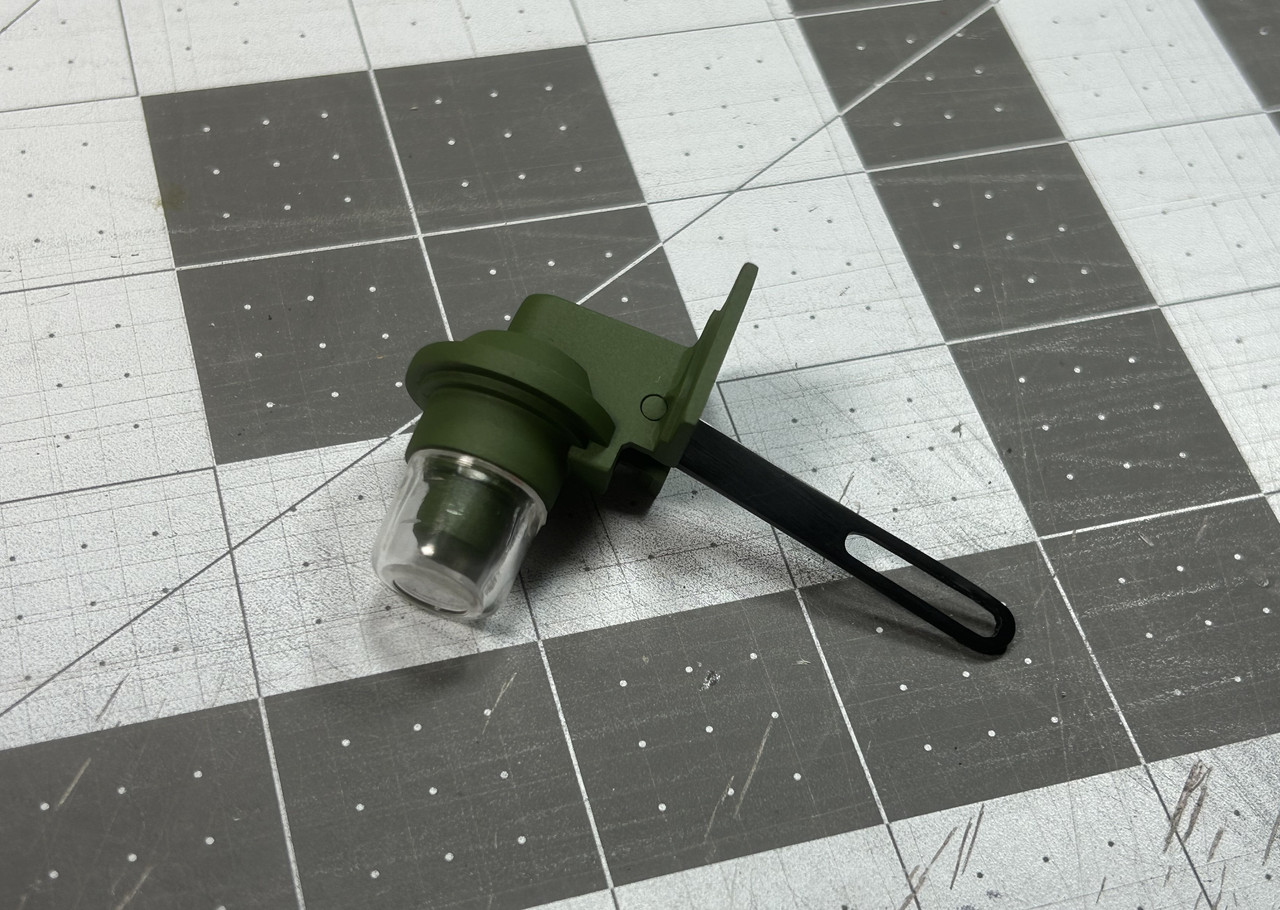
Figure V8020 through 022g: This image shows the vibration damper after painting and final assembly.
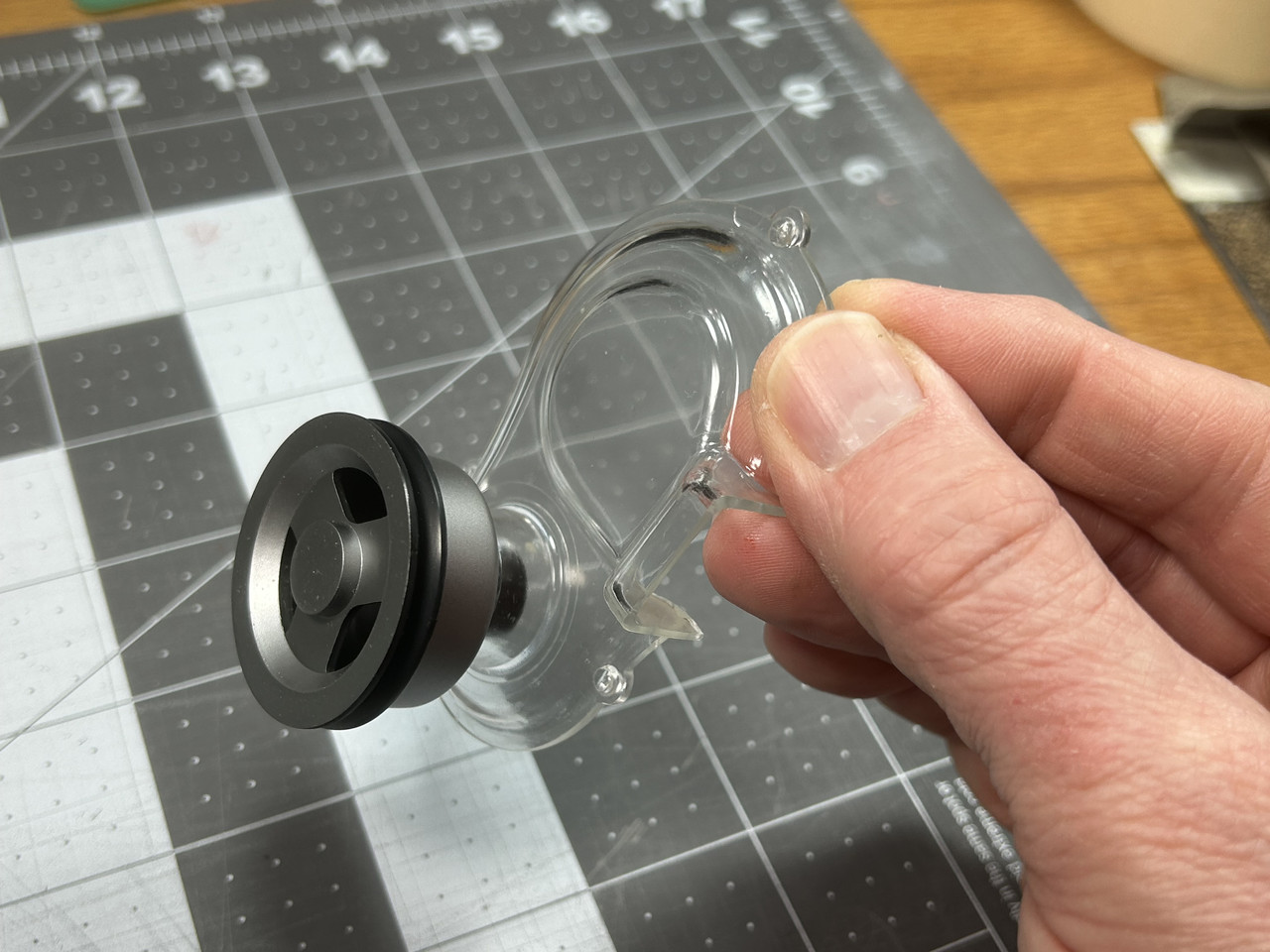
Until next time...
Phillip1
Re: Progress Build of a Holy Grail Model Display-Renwal’s Visible Automobile Chassis and Visible V8 Engine
Posted: Sat Mar 28, 2026 12:38 am
by digger303
Re: Progress Build of a Holy Grail Model Display-Renwal’s Visible Automobile Chassis and Visible V8 Engine
Posted: Sat Mar 28, 2026 7:55 am
by Stokesy44
Cracking post. The paintwork is flawless.
Can I ask what paints you use?
Re: Progress Build of a Holy Grail Model Display-Renwal’s Visible Automobile Chassis and Visible V8 Engine
Posted: Sat Mar 28, 2026 6:04 pm
by Phillip1
digger303/Stokesy44-Thank you very much!
Stokesy44-All of the paints used in the last post were either Model Master, Testors or Alclad enamels (thinned with Testors Enamel Thinner).
Phillip1
Re: Progress Build of a Holy Grail Model Display-Renwal’s Visible Automobile Chassis and Visible V8 Engine
Posted: Sat Mar 28, 2026 11:58 pm
by cor
You are doing a very fine job. What a crazy model. Almost a real car.
Re: Progress Build of a Holy Grail Model Display-Renwal’s Visible Automobile Chassis and Visible V8 Engine
Posted: Sun Mar 29, 2026 7:29 am
by Stokesy44
Phillip1 wrote: Sat Mar 28, 2026 6:04 pm
digger303/Stokesy44-Thank you very much!
Stokesy44-All of the paints used in the last post were either Model Master, Testors or Alclad enamels (thinned with Testors Enamel Thinner).
Phillip1
Thanks mate

Re: Progress Build of a Holy Grail Model Display-Renwal’s Visible Automobile Chassis and Visible V8 Engine
Posted: Sun Mar 29, 2026 3:33 pm
by Phillip1
cor-Thank you! I agree the kit is special. I have never seen or heard about another plastic model kit quite like it.
Phillip1
Re: Progress Build of a Holy Grail Model Display-Renwal’s Visible Automobile Chassis and Visible V8 Engine
Posted: Thu Apr 02, 2026 4:11 pm
by Phillip1
Fellow Modelers-Here is the next update.
Figure V8023: Step 23 is the pushrod installation.
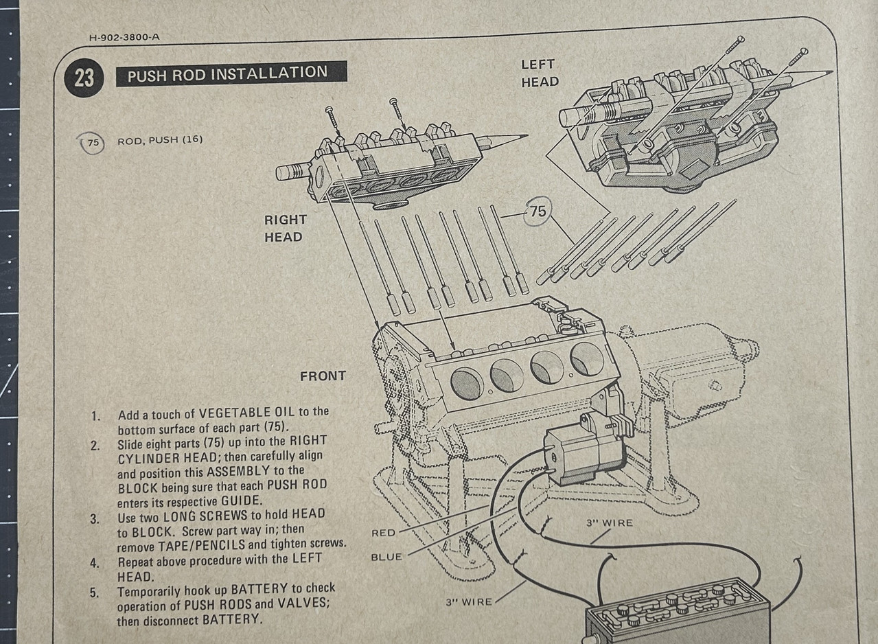
Figure V8023a: Here are the parts after being cleaned up.
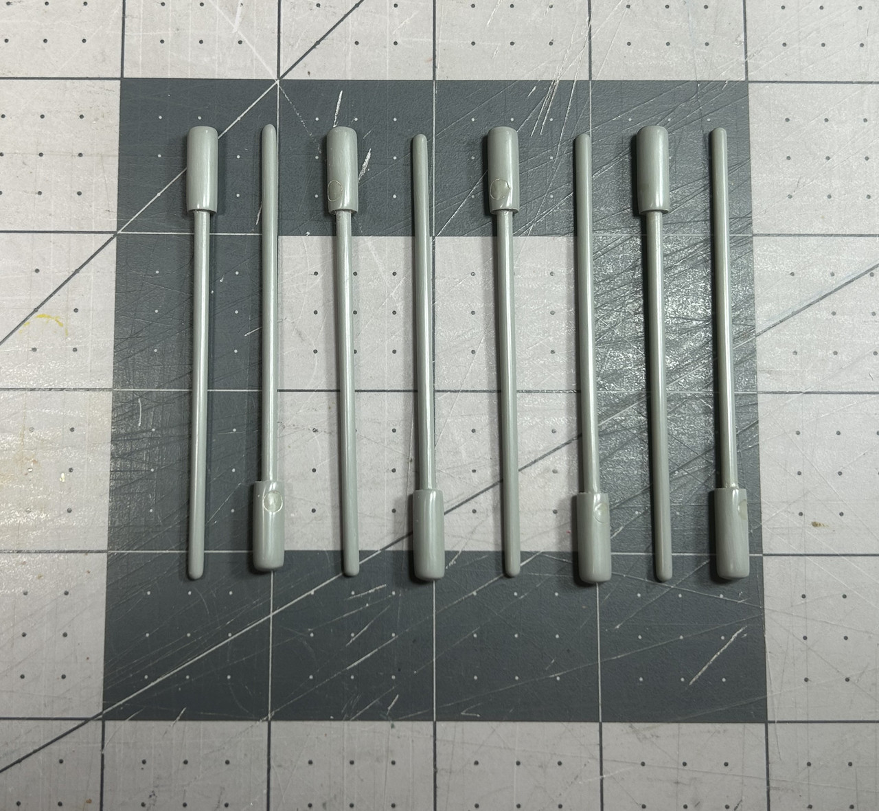
Figure V8023b: This image shows one side of the pushrods set in place.
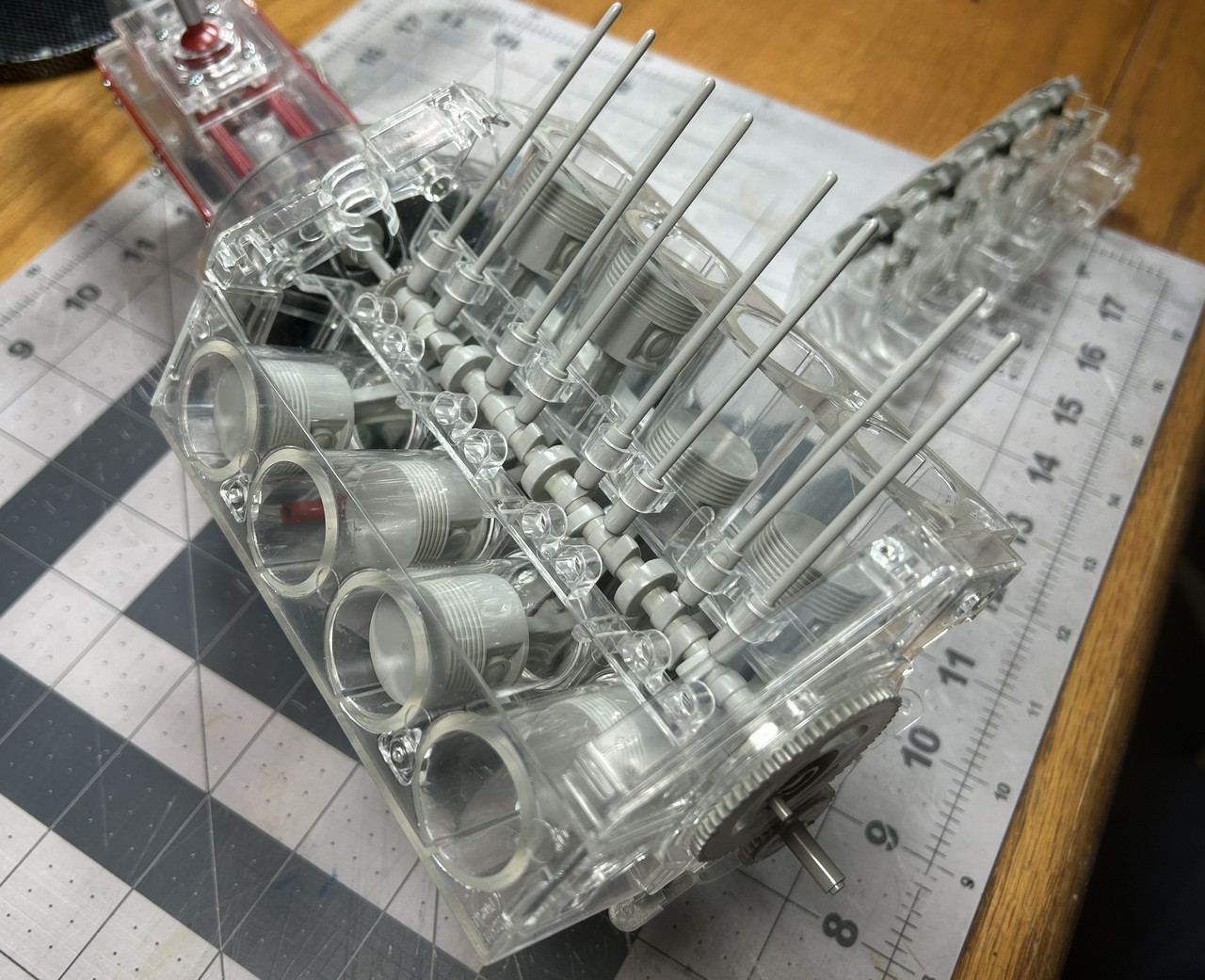
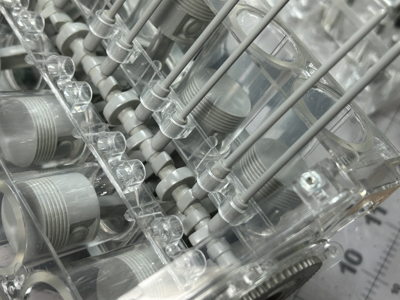
Figure V8023c: In this closeup image you can see how the pushrods line up on the camshaft. Because all the connecting parts were polished and had a slick finish no lubrication was required.
Figures V8023e through V8023g: These images show the progress of the engine at this point of the build.
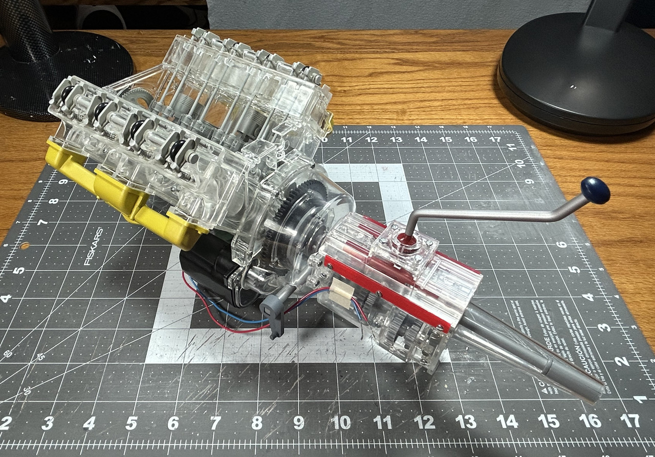
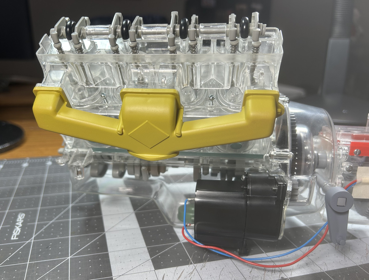
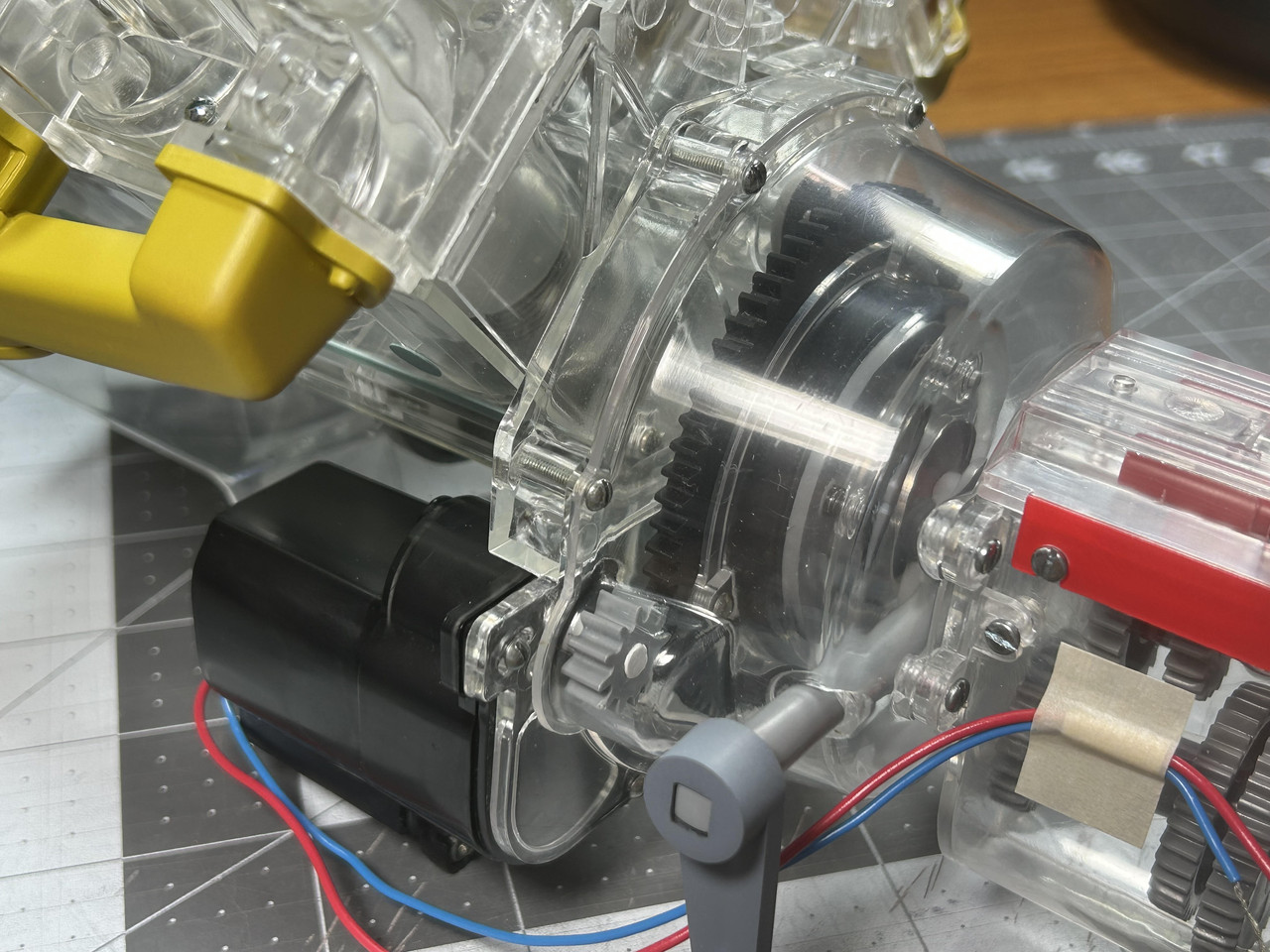
Figure V8024: Step 24 is the front components installation.
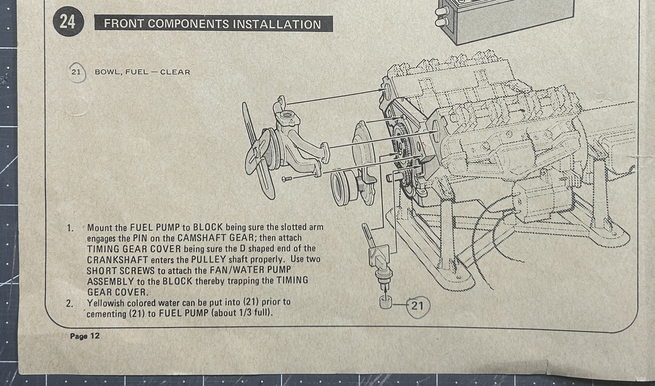
Figure V8024a: Here the fuel pump and vibration damper have been set in place. Note the black slotted fuel pump actuator arm is positioned over a raised pin on the large gear. When the gear rotates it causes the arm to move up and down.
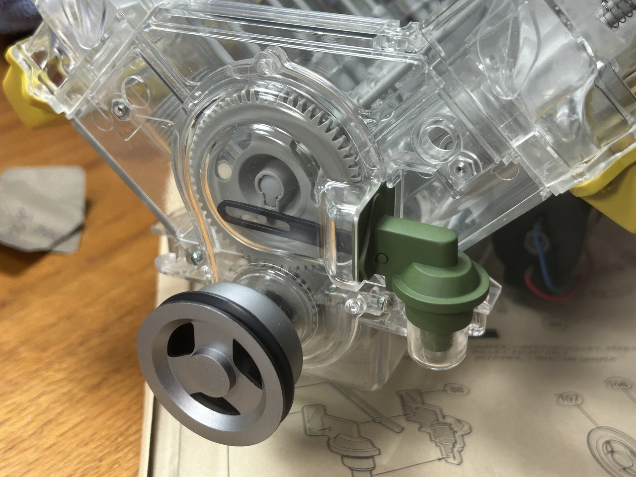
Figures V8024b through V8024c: The cooling fan/water pump are shown after being added to the engine.
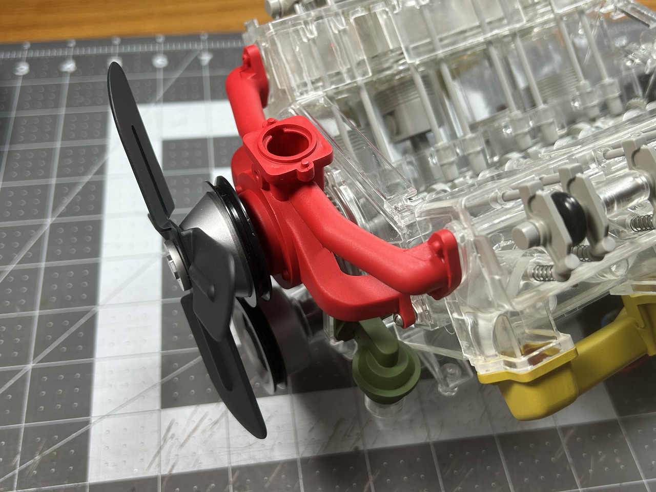
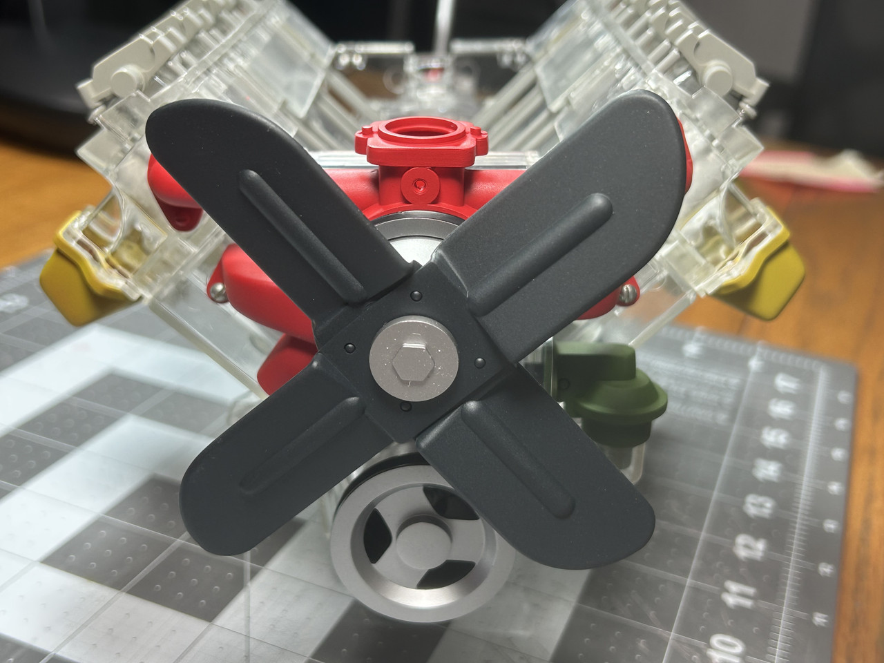
Figure V8025: Step 25 is the distributor assembly.
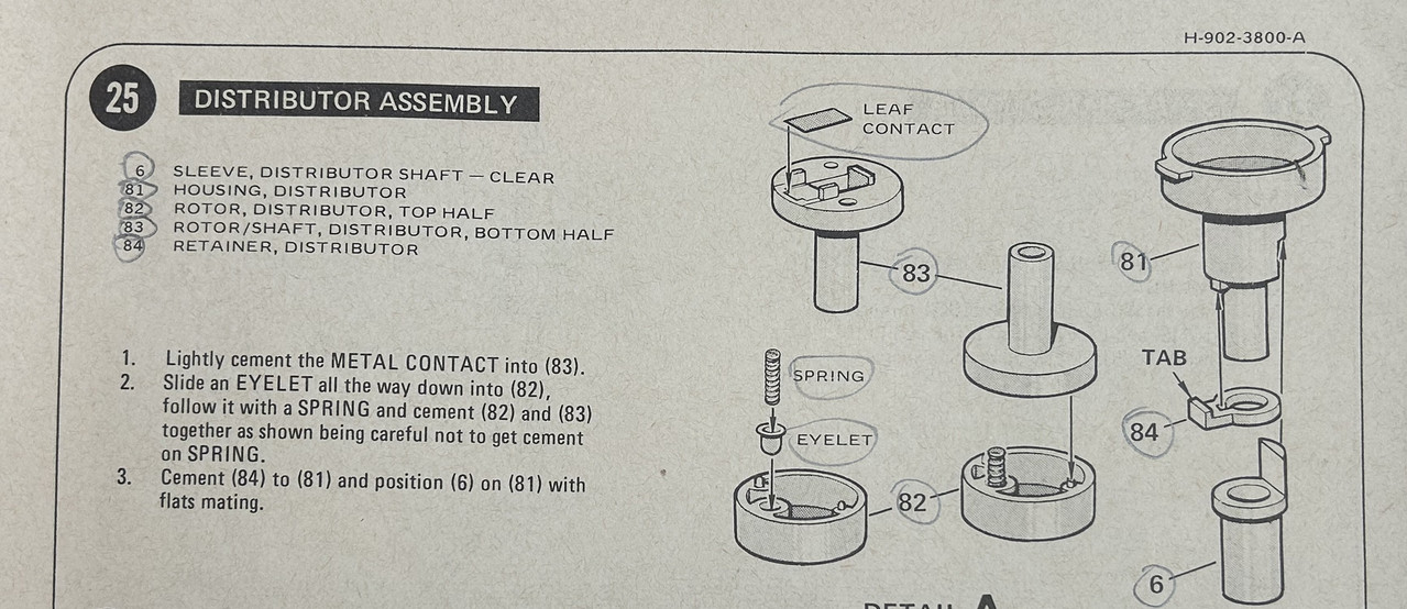
Figure V8025a: In this image the parts have been painted and are being test fitted before installation.
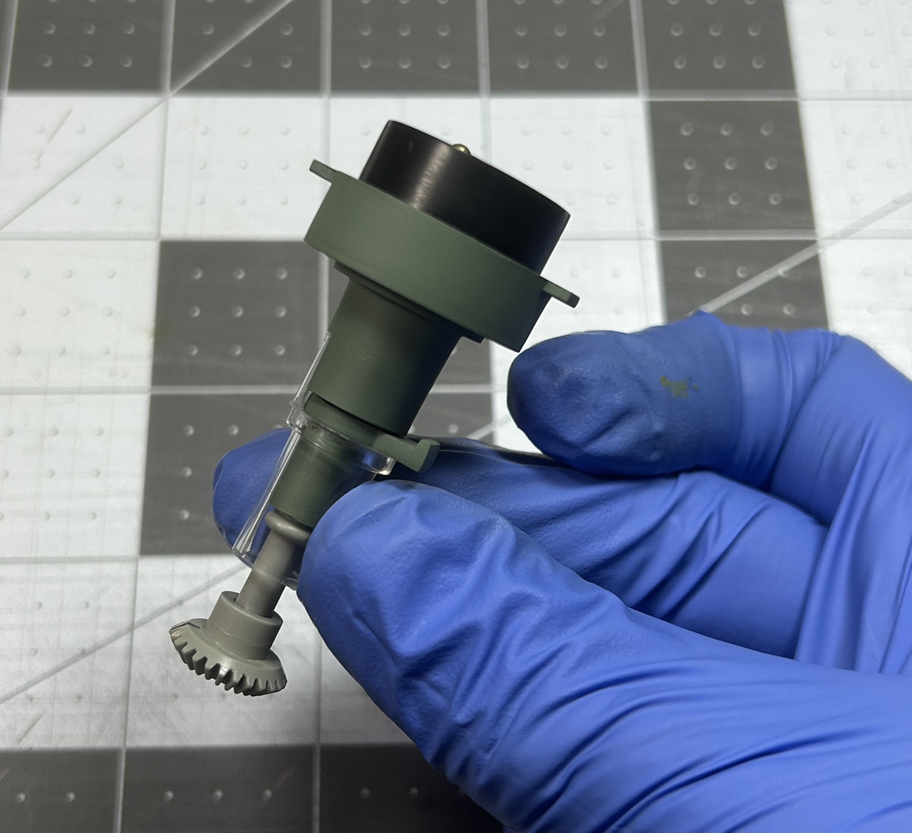
Figure V8026: Step 26 is the distributor and generator installation.
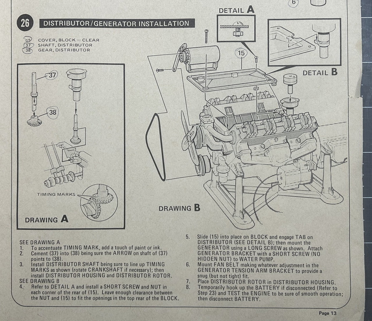
Figure V8026a: After the distributor assembly was snapped into place, the timing marks on the horizontal (distributor) and vertical (camshaft) gears were carefully lined up. These gears control the spark plug lights and pistons to operate in sync. A small amount of WD40 Specialist Silicon lubricant was applied to the gears to prevent sticking.
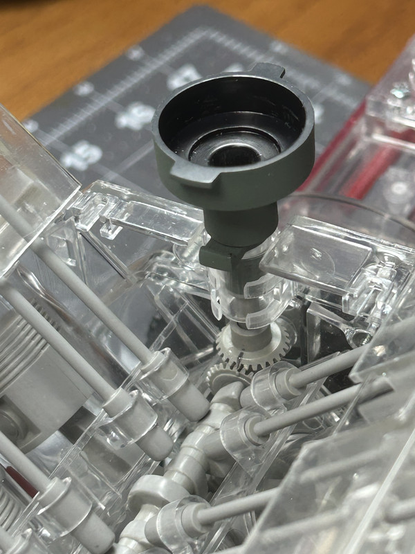
Figure V8026b: Here the black rotating top half of the distributor (which includes the spring loaded brass eyelet) has been set in place.
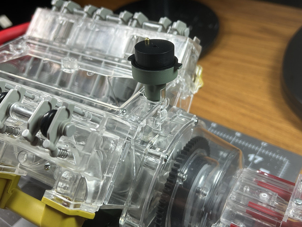
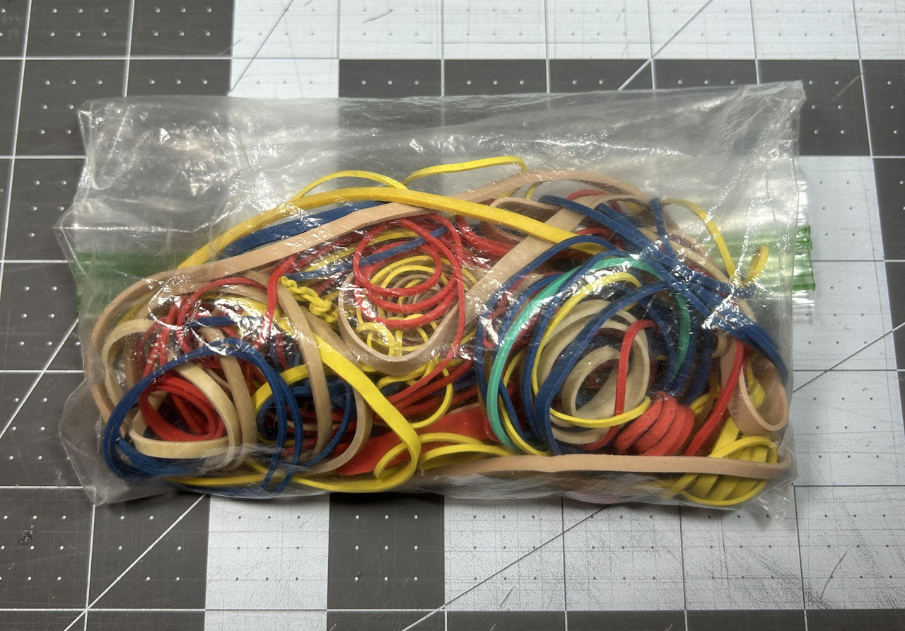
Figure V8026c: The Revell kit provides a small rubber band to represent the fan belt, but after 50 years it had no flexibility and could not be used. Therefore, I went through my big bag of rubber bands until one was found that did not hang loose, while not having too much tension to bend the shafts and pulleys. As Goldilocks would say it had to be “just right”.
Figures V8026d through V8026e: The rubber band has been added. The camshaft drives the vibration damper and the fan belt drives the cooling fan and generator. It’s actually pretty cool to see them turning during operation.
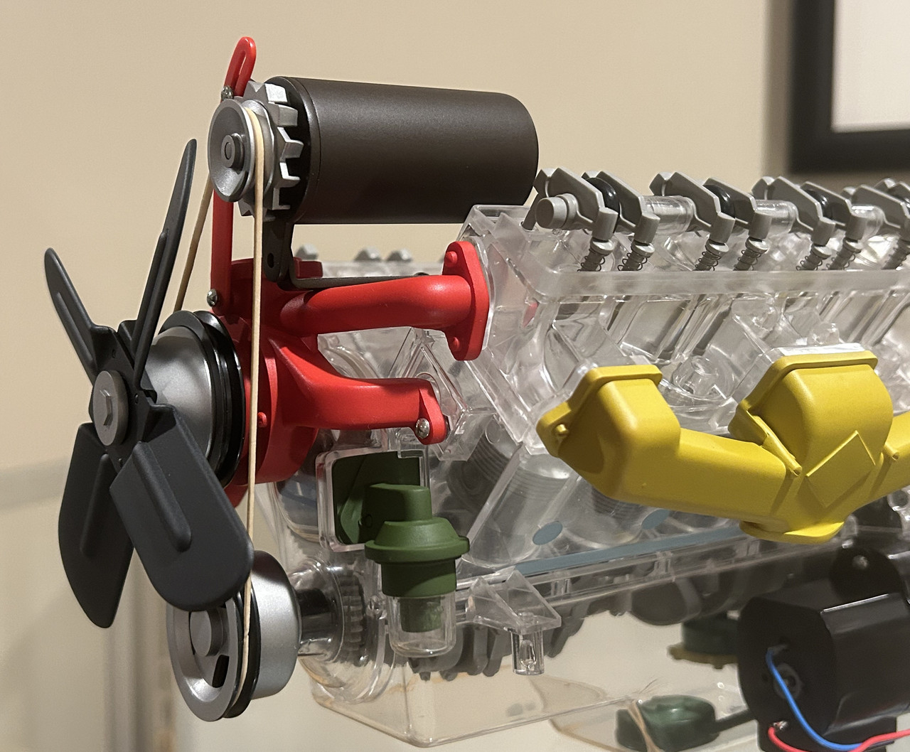
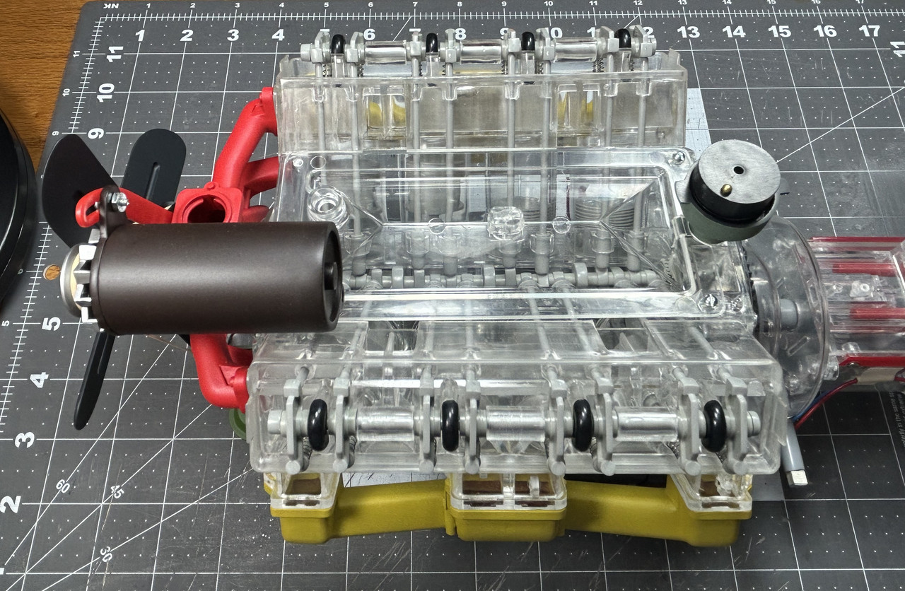
Figure V8027: Step 27 is the spark plug details.
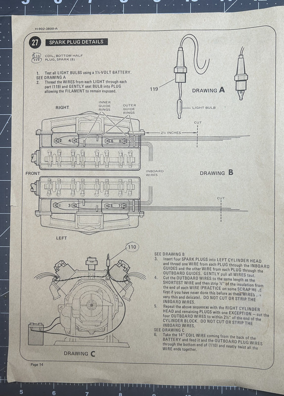
Figure V8027a: The Revell kit provides eight tiny “grain of wheat” red lights to represent firing spark plugs but one of mine did not work. I wanted all the lights to match so I found these replacements on eBay.
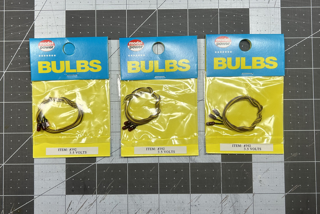
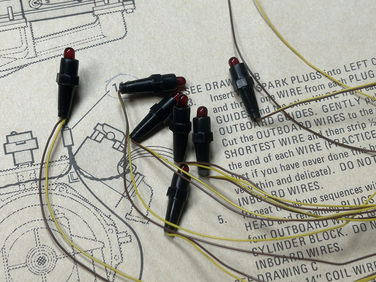
Figure V8027b: The tiny lights are threaded through the spark plugs.
Figures V8027c through V8027d: Next, the spark plugs were inserted into the openings of the cylinder heads.
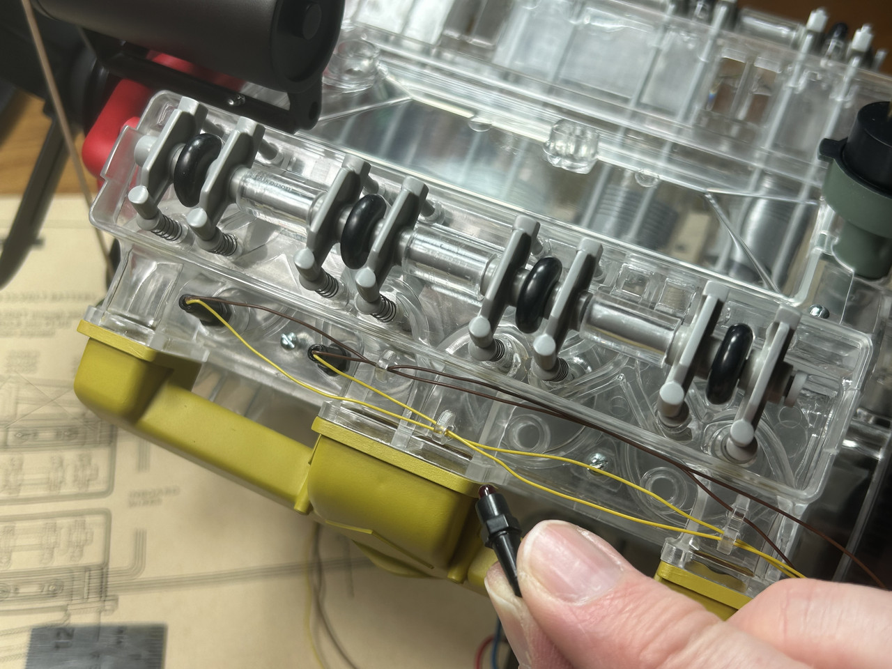
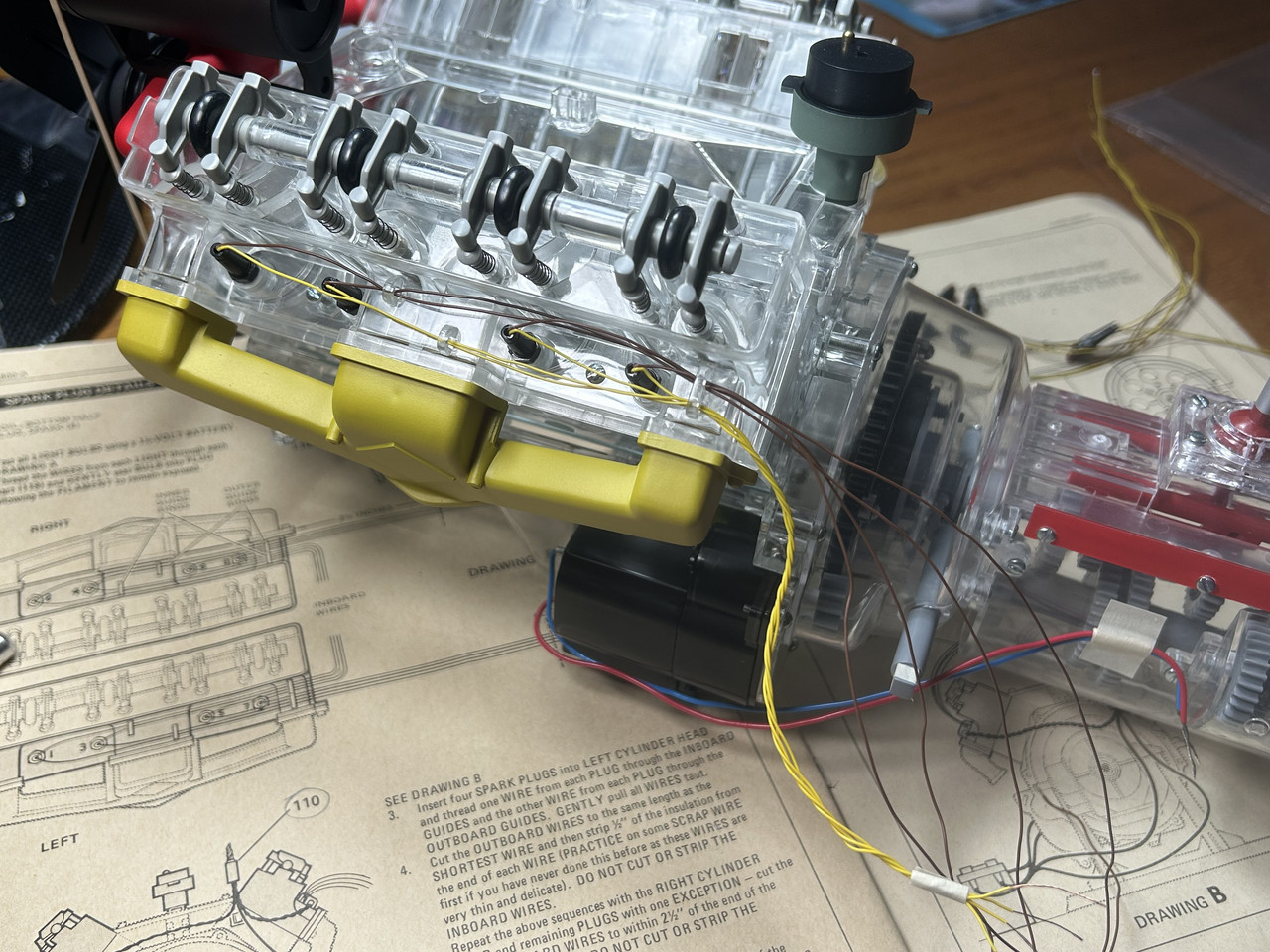
Figure V8027e: One half of all the spark plug light wires were connected to the battery/control box wiring per the instructions.
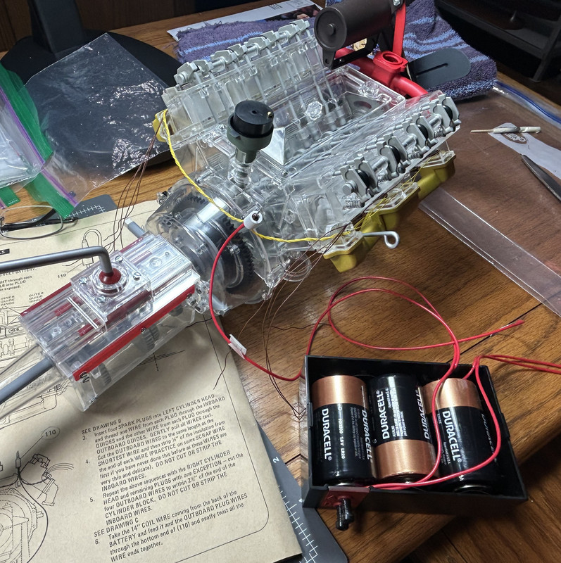
I am close to the finish line on this project! Until next time...
Phillip1
Re: Progress Build of a Holy Grail Model Display-Renwal’s Visible Automobile Chassis and Visible V8 Engine
Posted: Fri Apr 03, 2026 12:44 am
by digger303
Re: Progress Build of a Holy Grail Model Display-Renwal’s Visible Automobile Chassis and Visible V8 Engine
Posted: Fri Apr 03, 2026 8:07 am
by Stokesy44
Cracking work. Does the kit give you anything for the timing of each cylinder? I'm still enjoying the learning curve of how an internal combustion engine works.
Great Goldilocks reference too!

Re: Progress Build of a Holy Grail Model Display-Renwal’s Visible Automobile Chassis and Visible V8 Engine
Posted: Fri Apr 03, 2026 4:20 pm
by Phillip1
digger303-Your comment makes me "happy" and "happier"!
Stokesy44-Thank you very much! Back in Step 7 the gears on the crankshaft and camshaft were sync together so the cylinder pistons and rockers arms would move in unison with each other when the electric motor is engaged. I guess it is not too often you see Goldilocks referenced on a plastic model website!
Phillip1
Re: Progress Build of a Holy Grail Model Display-Renwal’s Visible Automobile Chassis and Visible V8 Engine
Posted: Sat Apr 04, 2026 7:05 am
by cor
Truly awesome
Re: Progress Build of a Holy Grail Model Display-Renwal’s Visible Automobile Chassis and Visible V8 Engine
Posted: Sun Apr 05, 2026 7:56 pm
by Phillip1
cor-Thanks!
Phillip1
Re: Progress Build of a Holy Grail Model Display-Renwal’s Visible Automobile Chassis and Visible V8 Engine
Posted: Wed Apr 08, 2026 5:19 pm
by Phillip1
Fellow Modelers-This is the last Progress Build Post.
Figure V8028: Step 28 is the distributor hook up.
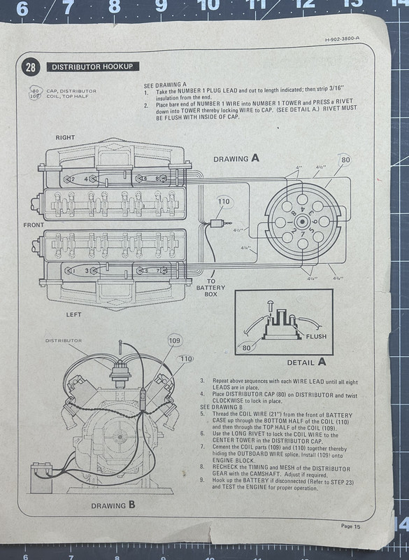
Figure V8028a: A red wire from the battery/control box was run through the black and white coil to get it closer to the top of the distributor where it will be connected later.
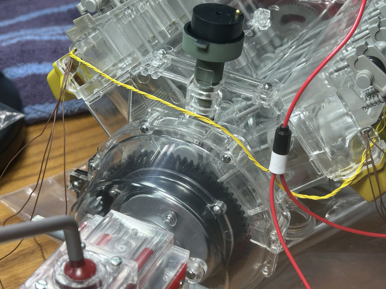
Figures V8028b through V8028c: The remaining half of the spark plug light wires were now run through individual holes in the distributor cap and fixed in place with short, metal rivets. Each wire had to go in a specific hole to get the spark plug lights to fire in the correct sequence. The rivets also had to be flush with the plastic on the inside of the distributor cap.
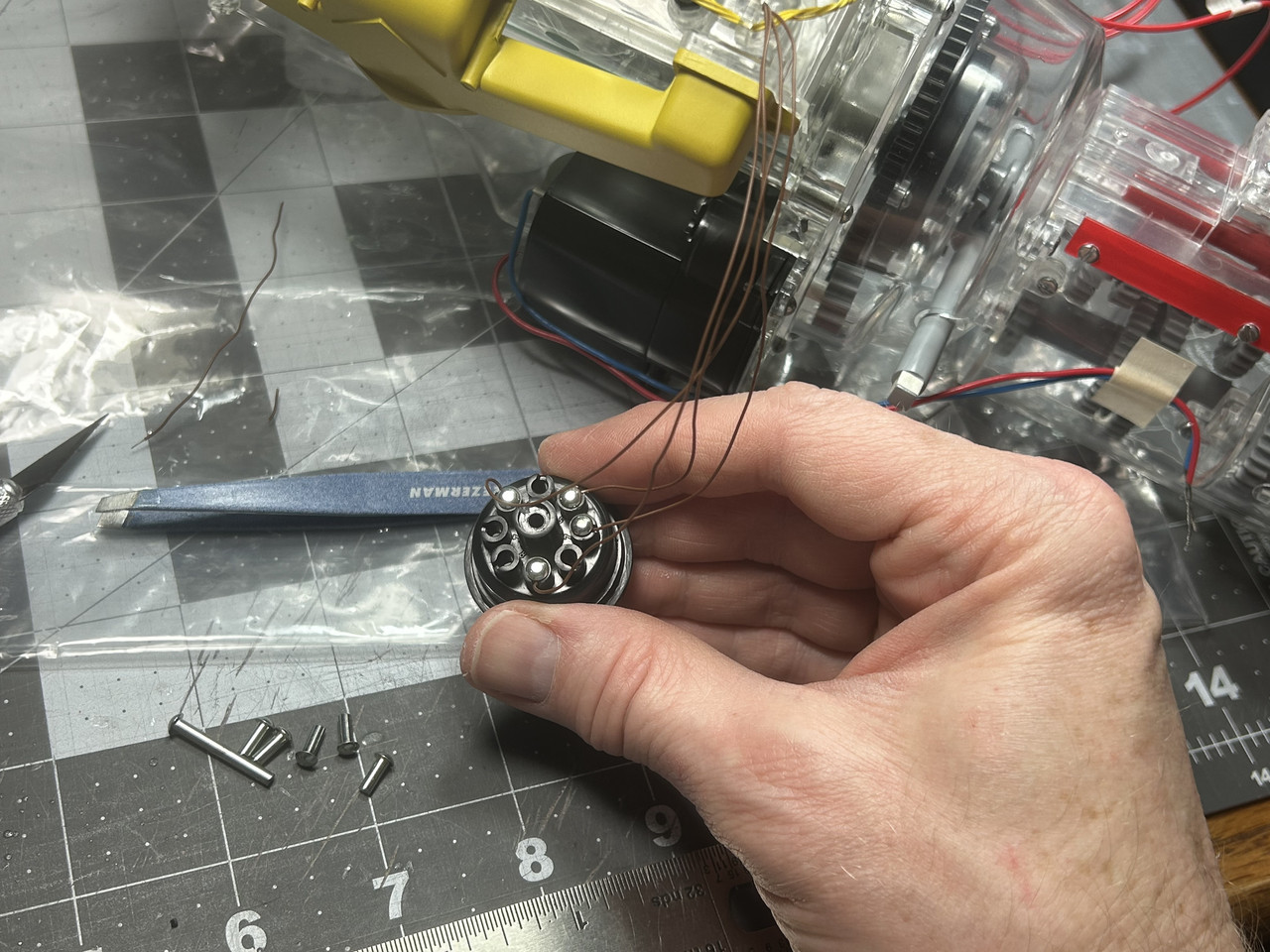
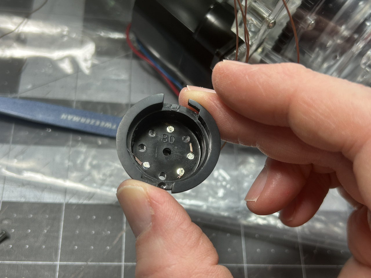
Figure V8028d: Per the instructions the remaining red wire from the battery/control box was supposed to be wrapped around a long rivet and put in the distributor cap center hole to make a connection with a metal leaf. However, the only way I could get it to work was by discarding the long rivet and feeding the live wire into the hole until it directly touched the leaf. Once the position was set, I glued the wiring in place so it would not move.
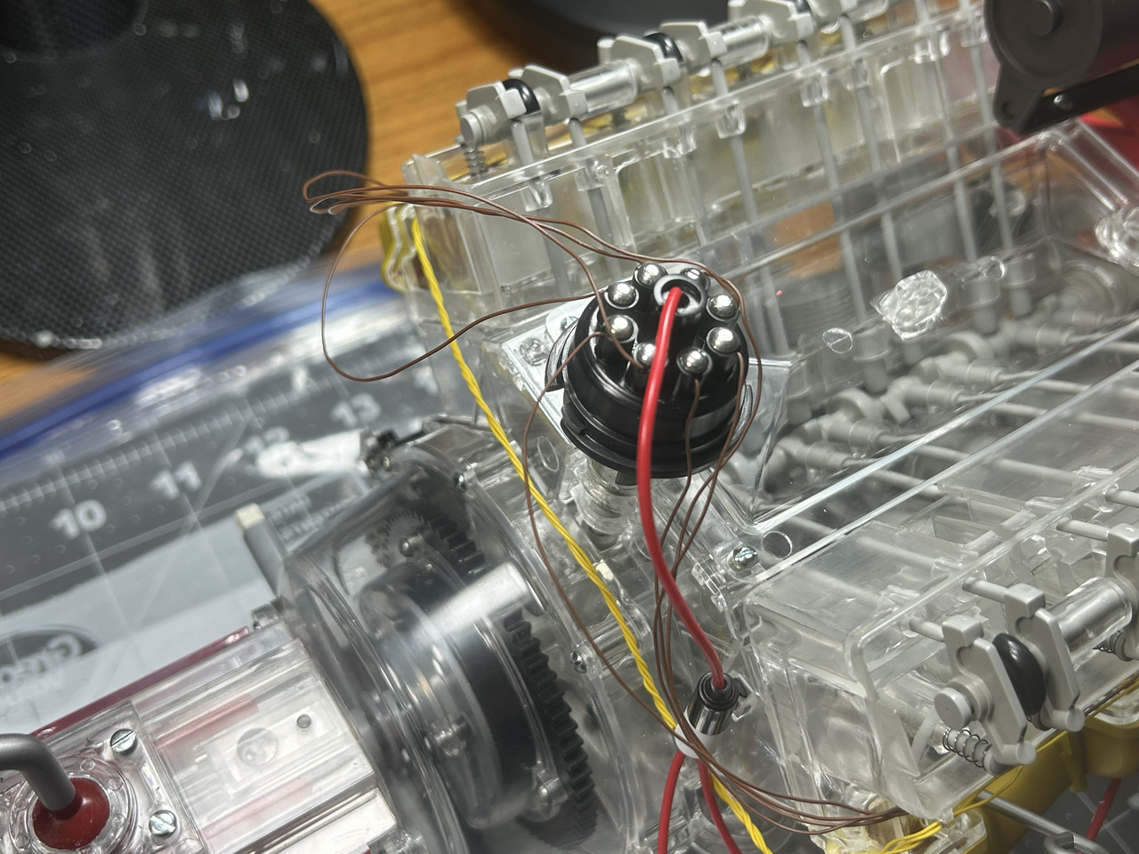
At this point I had a pretty scary mishap occur with the build. When I first pushed the control box button to test everything (i.e., spark plug lights along with all the other moving parts) the spark plug lights came on but then went off immediately. A few seconds later the moving parts started to sound funny (not ha! ha! funny). Then I noticed the back half of the rocker arms and push rods were no longer moving-AT ALL! To my great dismay the camshaft (a solid plastic part) had broken in half, right in the middle. I could not believe it...but (once I was able to stop my uncontrollable sobbing) I did some disassembly work to see what repairs could be done. A quick inspection revealed the small gear at the bottom of the distributor assembly was pushed down too low, binding the camshaft gear and preventing it from rotating which caused the break. Right away I noticed the camshaft break was very clean and it did not take much manipulation to push the two halves back together. Once this was done, I started very carefully applying small amounts of superglue at the break. This produced a strong connection and allowed me to slowly rotate the camshaft where I could apply superglue around the entire damaged area. Once all the parts were cleaned up and re-assembled, I did another test run and everything (including the sequenced spark plug lights) worked great and ran smooth! I consider myself very fortunate that this repair could be made.
Figure V8028f: Small pieces of masking tape were used hold the wires together and make everything look neater.
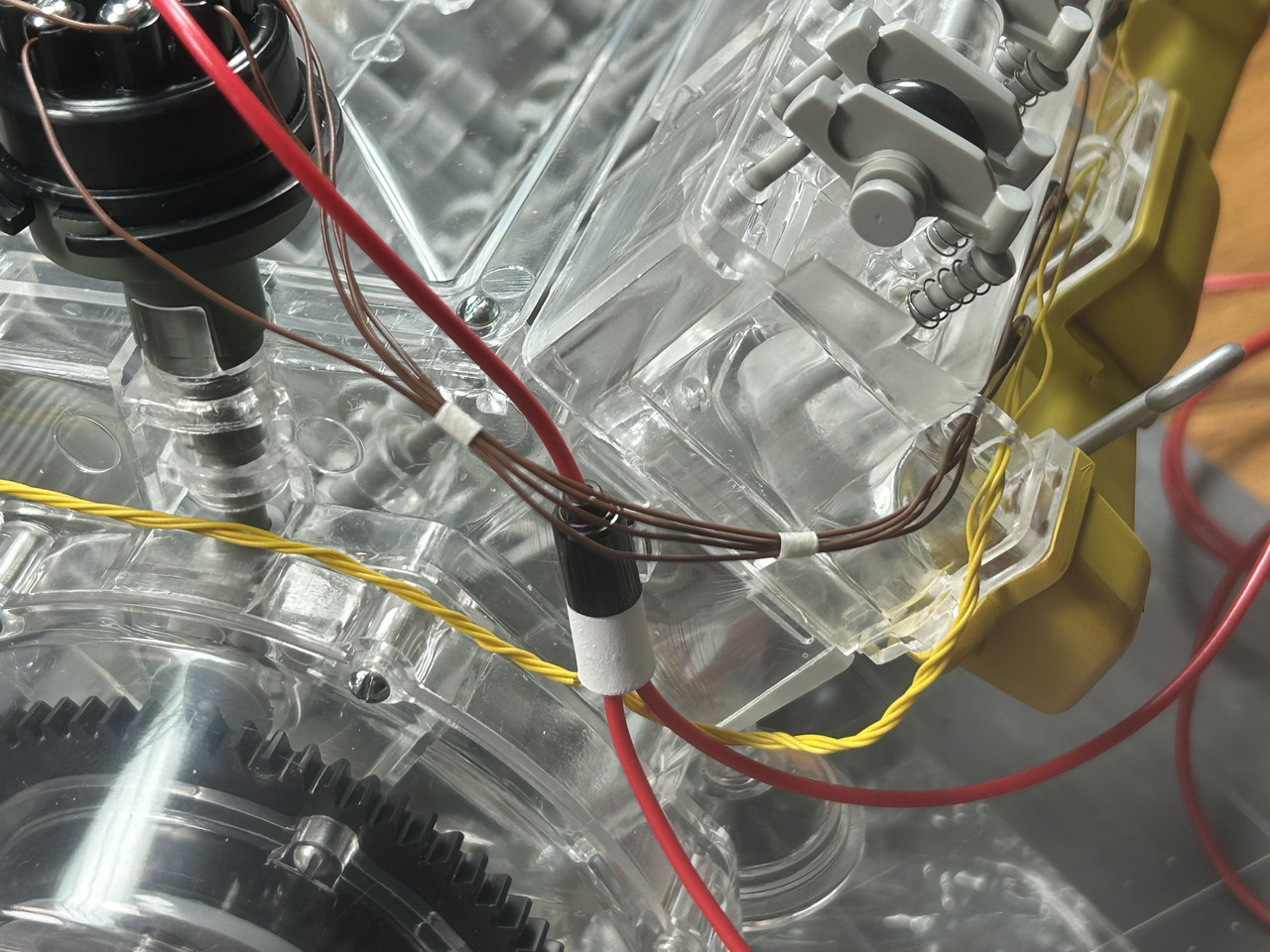
Figure V8029: Step 29 is the final assembly of the engine.
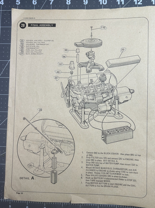
Figures V8029a through V8029b: Here are the parts after being cleaned up and then after being painted.
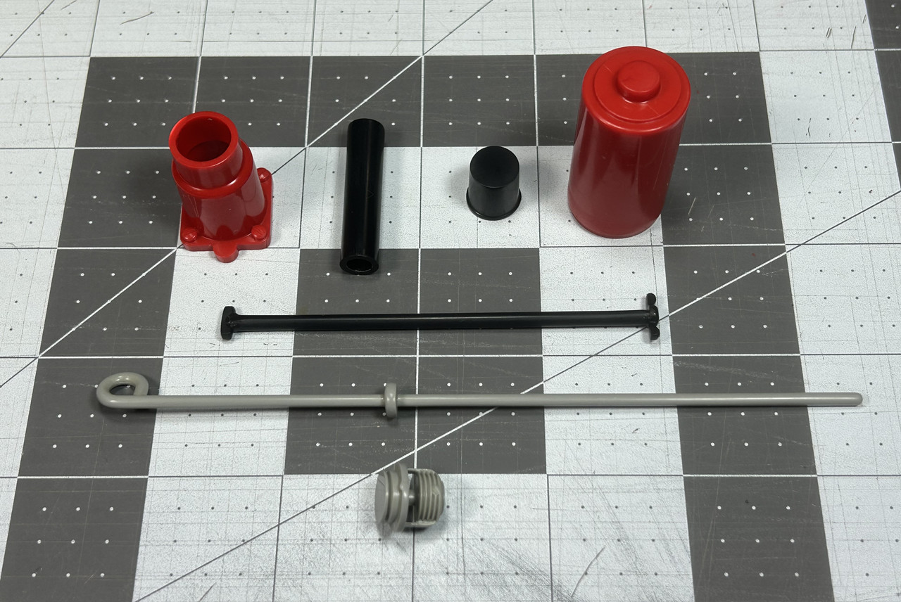
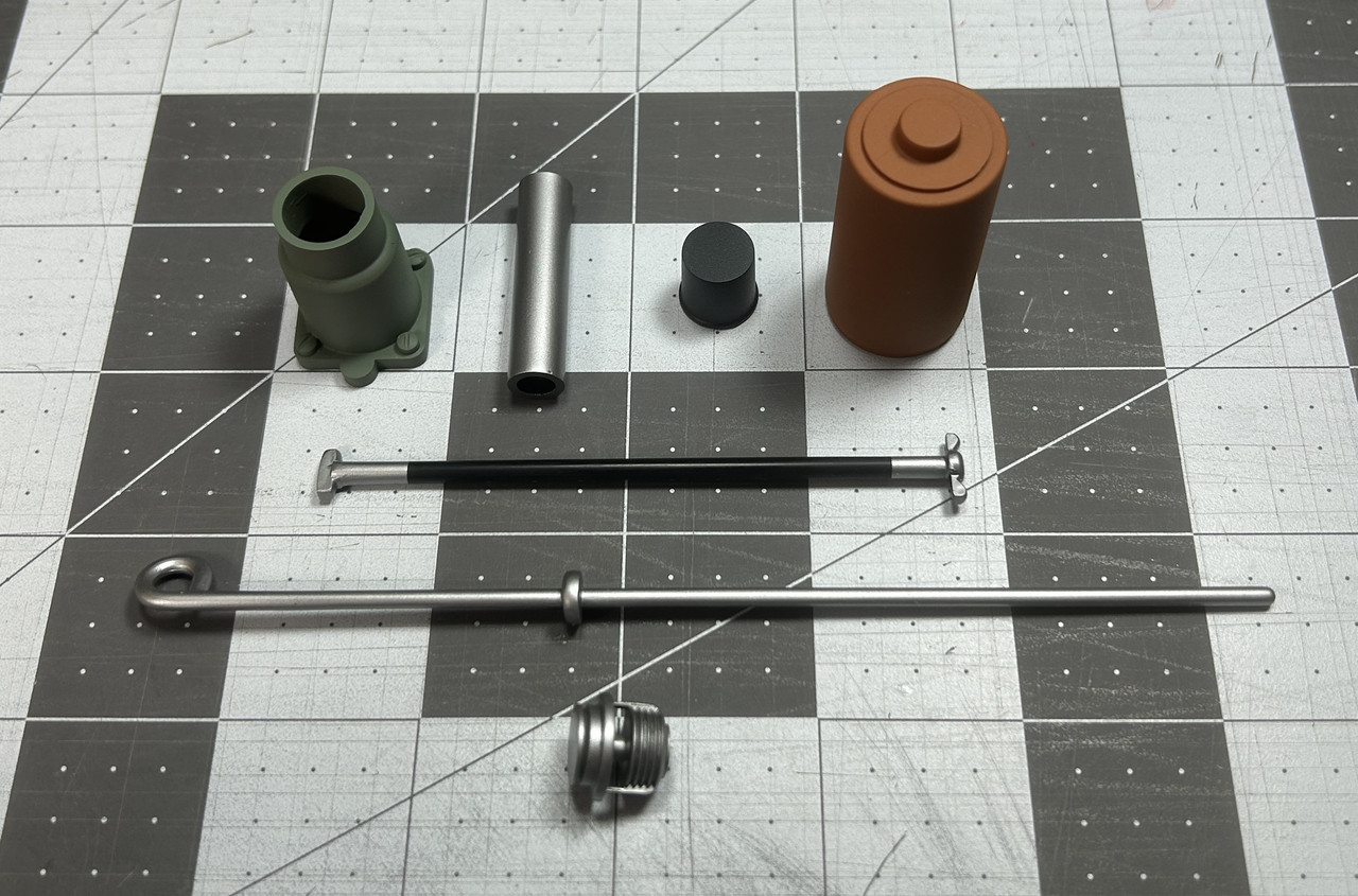
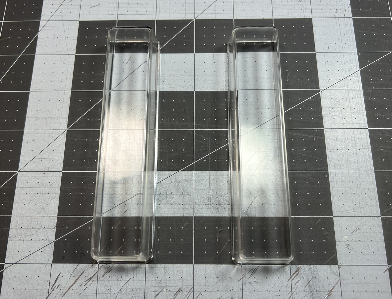
Figure V8029c: The clear valve covers were the last parts added.
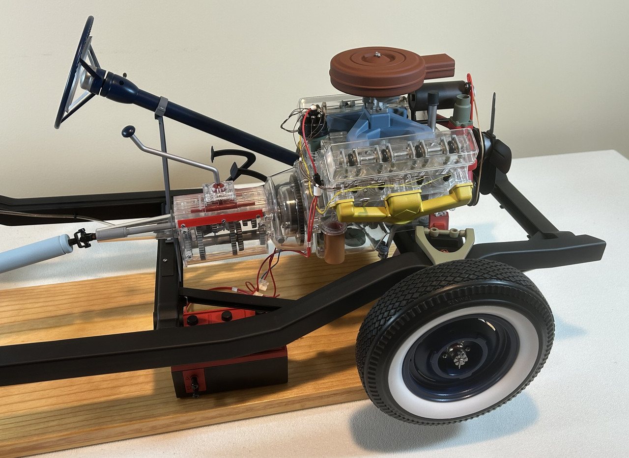
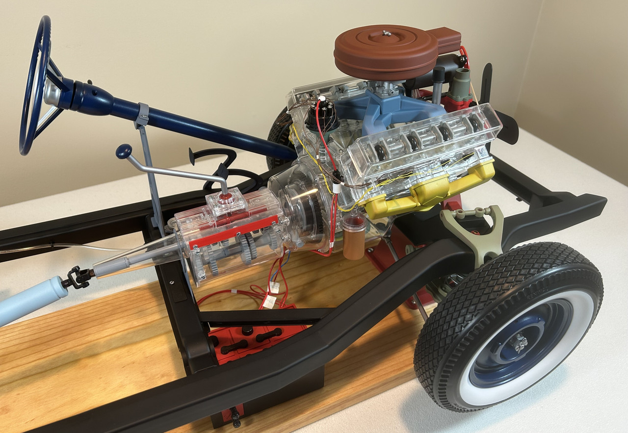
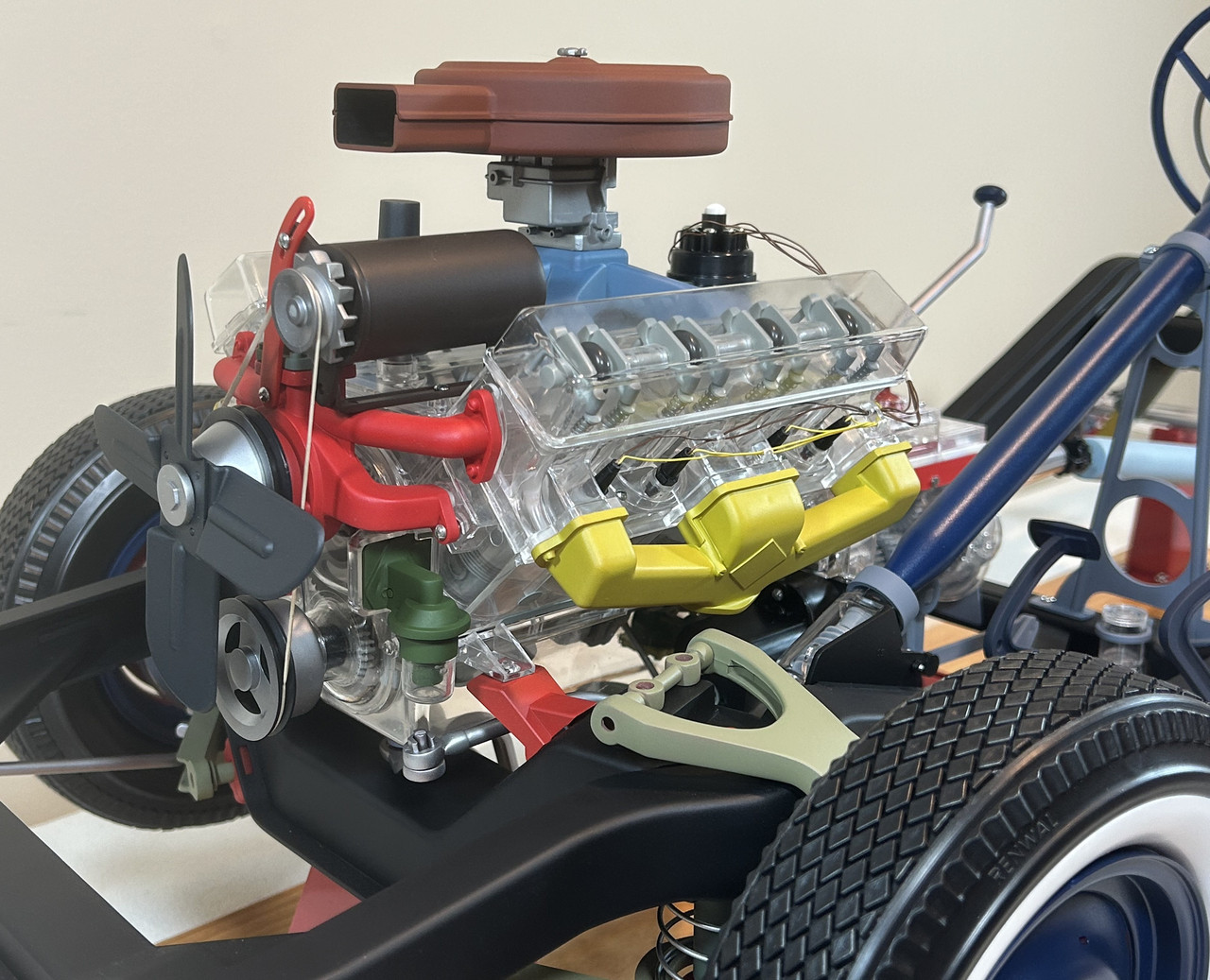
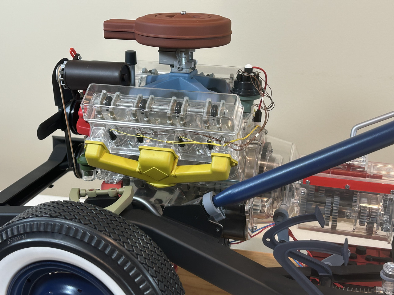
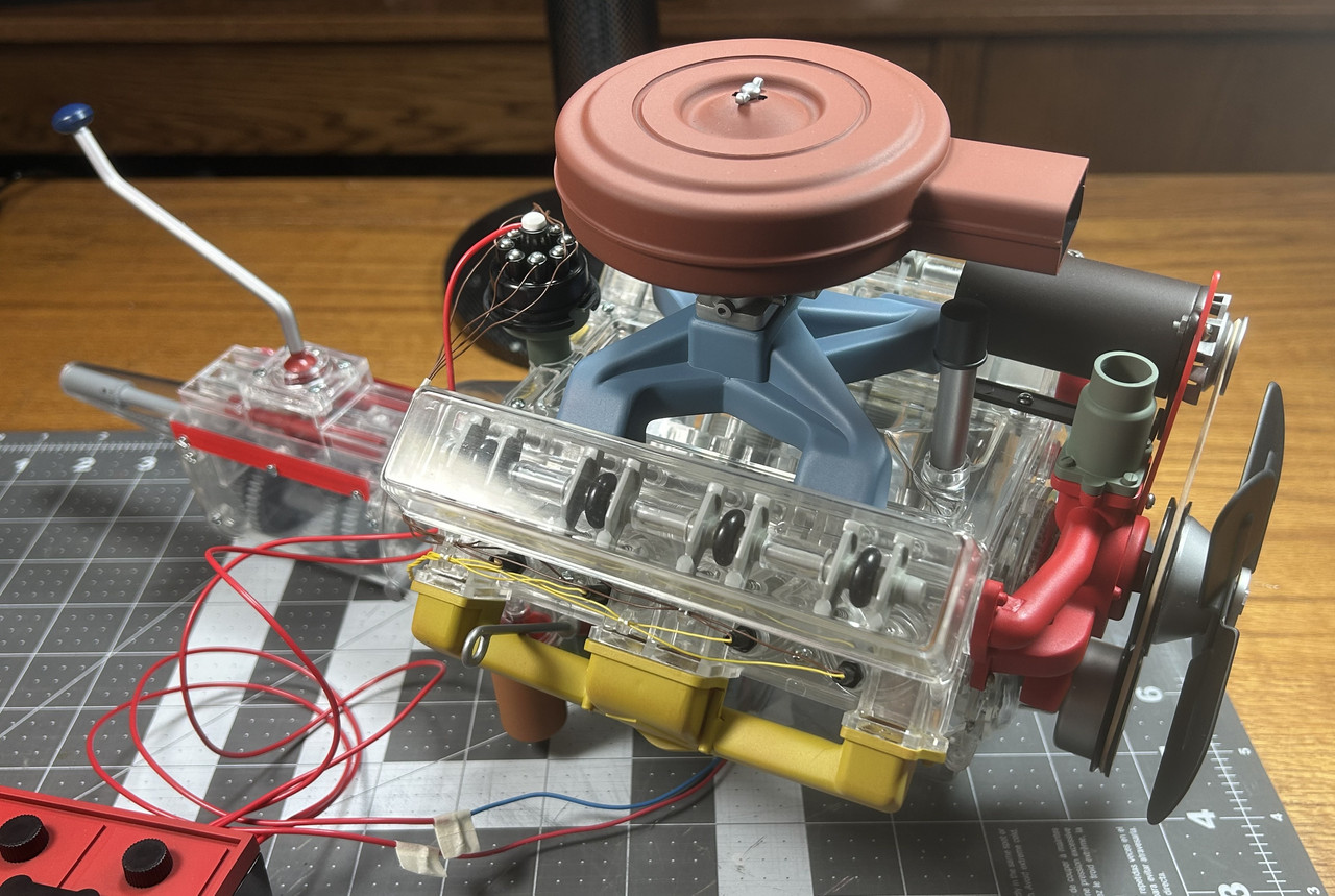
Figures V8029d through V8029g: The V8 engine is finished! Here are some informal images of it. About 115 hours were required for the build, with about half of that spent cleaning up and modifying the kit parts. The biggest challenge with this model was making sure all the moving parts operated without any binding. They were all interconnected like a chain and anytime one link broke or did not move like it was supposed to, it caused a lot of headaches.

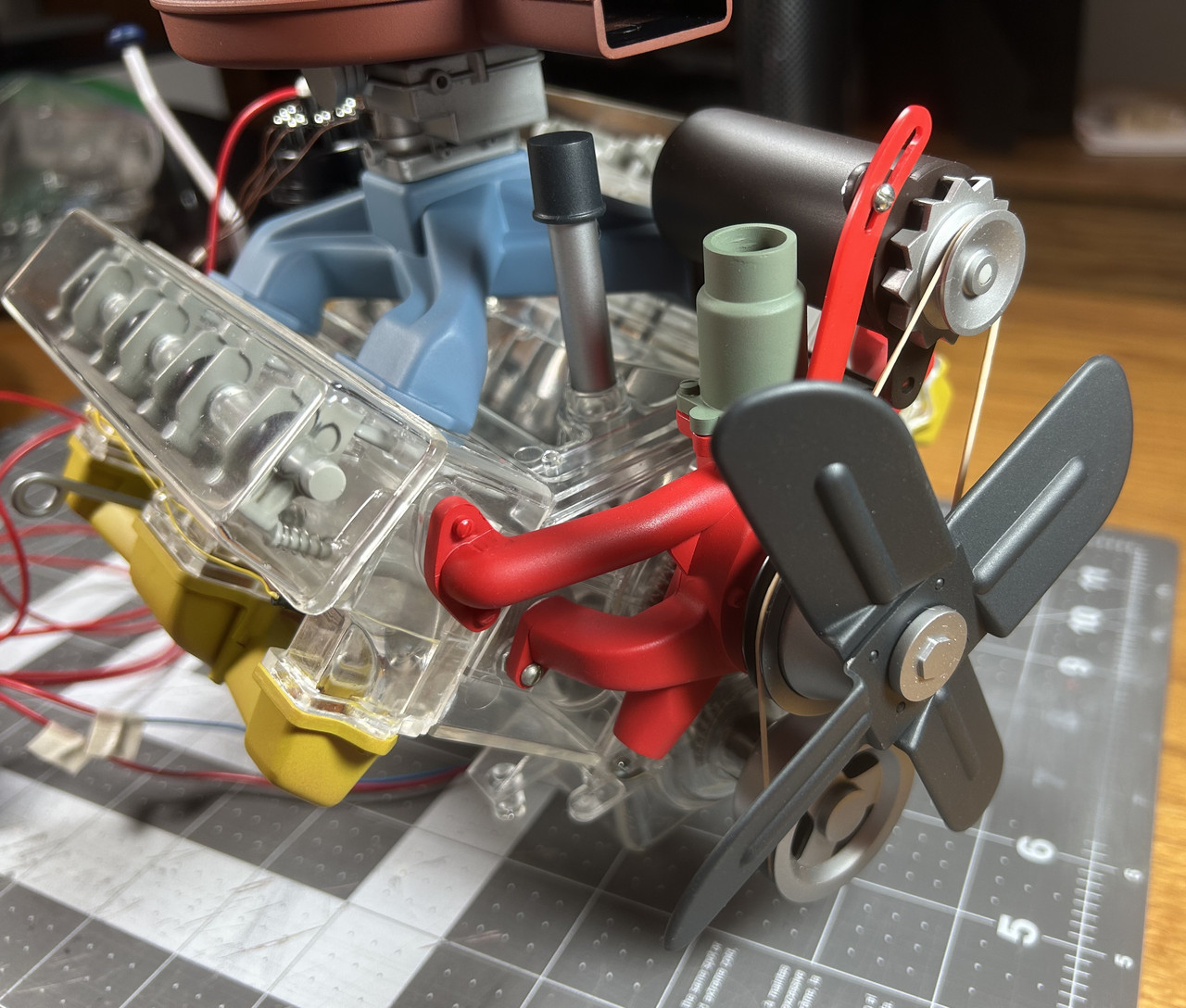

Figures V8029h through V8029i: These two images were taken while the engine was up and running. You can kind of see the cooling fan and generator pulley are blurred from movement. Also, you can see the red glow produced by the spark plug lights (first at the front and then at the rear). There is too much light and glare to see the red glow on the side closest to the camera.
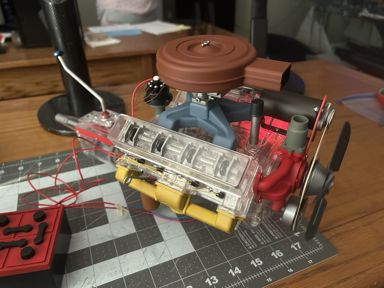
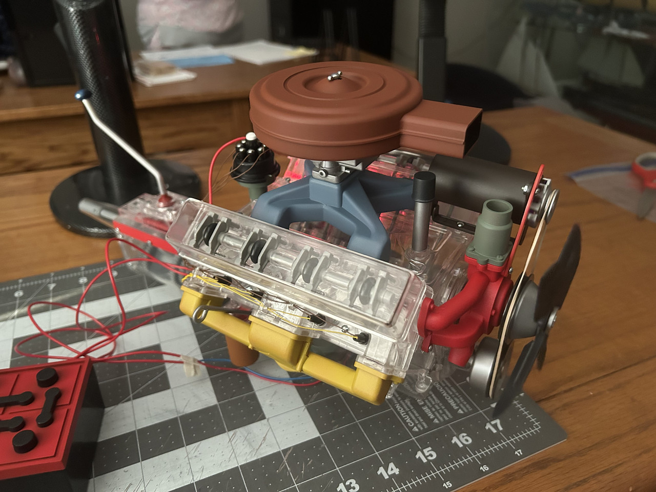
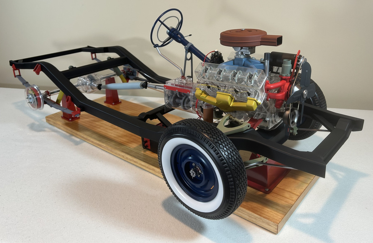
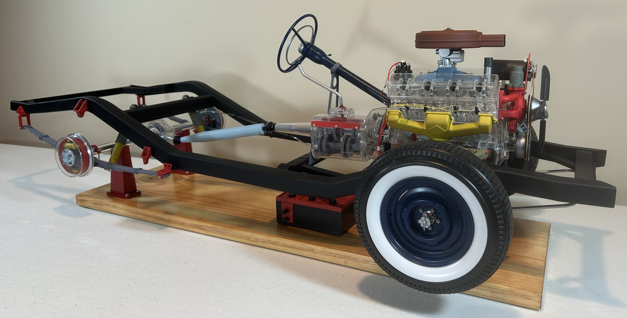
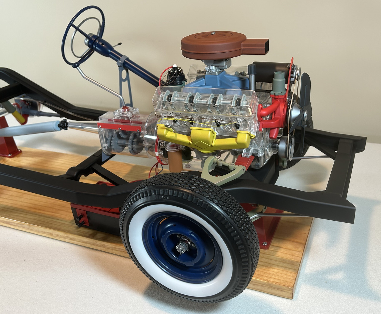
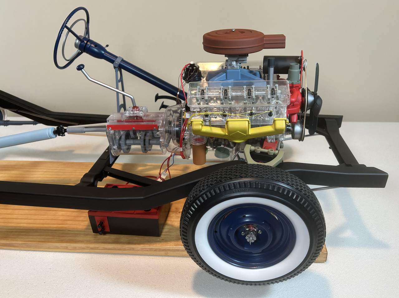
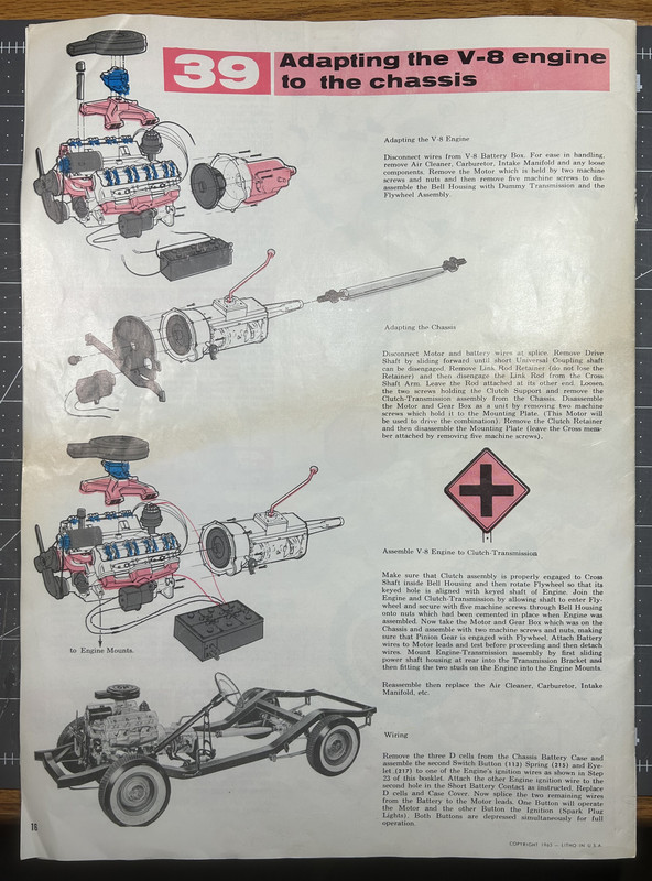
Figure V8029l: The last step of the project is mounting the V8 engine to the chassis and reconnecting a few odds and ends.
I hope to be able to post formal images of the finished project in the next couple of days.
Until next time...
Phillip1
Re: Progress Build of a Holy Grail Model Display-Renwal’s Visible Automobile Chassis and Visible V8 Engine
Posted: Wed Apr 08, 2026 10:36 pm
by Stokesy44
Looking really good, can't wait for the next step to finish it. Will you be positing a video so we can see it working?

Re: Progress Build of a Holy Grail Model Display-Renwal’s Visible Automobile Chassis and Visible V8 Engine
Posted: Thu Apr 09, 2026 2:51 pm
by Phillip1
Stokesy44-Thanks. The finish line is very near! I would love to post some short operation videos but do not know how.

If you know how, please share it with me!
Phillip1
Re: Progress Build of a Holy Grail Model Display-Renwal’s Visible Automobile Chassis and Visible V8 Engine
Posted: Thu Apr 09, 2026 6:45 pm
by Stokesy44
Phillip1 wrote: Thu Apr 09, 2026 2:51 pm
Stokesy44-Thanks. The finish line is very near! I would love to post some short operation videos but do not know how.
If you know how, please share it with me!
Phillip1
Leave it with me. I know it can be done, I'll check with some of the guys who have done it and will get back to you
Re: Progress Build of a Holy Grail Model Display-Renwal’s Visible Automobile Chassis and Visible V8 Engine
Posted: Thu Apr 09, 2026 8:29 pm
by Phillip1
Stokesy44-
Phillip1
Re: Progress Build of a Holy Grail Model Display-Renwal’s Visible Automobile Chassis and Visible V8 Engine
Posted: Fri Apr 10, 2026 7:06 am
by Stokesy44
Phillip1 wrote: Thu Apr 09, 2026 8:29 pm
Stokesy44-
Phillip1
I asked the eggheads about videos and was advised of the following:
We cannot host videos (they are too big). What you can do is host the video with a known provider like Vimeo or YouTube and then link the video to your thread.
I do this with the new releases thread. I just copy the URL from YouTube and drop it into the thread.
I hope this helps
Re: Progress Build of a Holy Grail Model Display-Renwal’s Visible Automobile Chassis and Visible V8 Engine
Posted: Fri Apr 10, 2026 1:22 pm
by Phillip1
Stokesy44-Thanks for the information. Does an account have to be set up with YouTube? Is there a cost to do this?
Phillip1
Re: Progress Build of a Holy Grail Model Display-Renwal’s Visible Automobile Chassis and Visible V8 Engine
Posted: Fri Apr 10, 2026 6:26 pm
by Stokesy44
Phillip1 wrote: Fri Apr 10, 2026 1:22 pm
Stokesy44-Thanks for the information. Does an account have to be set up with YouTube? Is there a cost to do this?
Phillip1
Hi, I'm pretty sure YouTube is free. You set up your own channel (account) and load videos on to the channel.
Re: Progress Build of a Holy Grail Model Display-Renwal’s Visible Automobile Chassis and Visible V8 Engine
Posted: Sat Apr 11, 2026 3:21 pm
by Phillip1
Stokesy44-Thanks!
Phillip1
Re: Progress Build of a Holy Grail Model Display-Renwal’s Visible Automobile Chassis and Visible V8 Engine
Posted: Sun Apr 12, 2026 1:01 am
by Phillip1
Re: Progress Build of a Holy Grail Model Display-Renwal’s Visible Automobile Chassis and Visible V8 Engine
Posted: Sun Apr 12, 2026 3:38 am
by digger303
Re: Progress Build of a Holy Grail Model Display-Renwal’s Visible Automobile Chassis and Visible V8 Engine
Posted: Sun Apr 12, 2026 6:50 am
by Stokesy44
Fantastic build and thread.
I loved the videos at the end, especially when you could see the individual cylinders firing in sequence, complete with lights showing each one as it sparked.
Re: Progress Build of a Holy Grail Model Display-Renwal’s Visible Automobile Chassis and Visible V8 Engine
Posted: Mon Apr 13, 2026 1:33 pm
by Phillip1
digger303/Stokesy44-Thank you very much!

Phillip1
Re: Progress Build of a Holy Grail Model Display-Renwal’s Visible Automobile Chassis and Visible V8 Engine
Posted: Sun Apr 19, 2026 1:31 am
by DRUMS01
Wonderful build of a very rare and old kit. The modeling thread was a very enjoyable read. Your modeling skills and fortitude in seeing this through provides us with an amazing model. I can only imagine the wonder and excitement it would cause if shown at an IPMS modeling event.
Kudo's....
Re: Progress Build of a Holy Grail Model Display-Renwal’s Visible Automobile Chassis and Visible V8 Engine
Posted: Sun Apr 19, 2026 9:19 pm
by Phillip1
DRUMS01-Thanks for the great comments! A long time ago (in a galaxy far, far away) I was an IPMS member and frequently attended local shows and national contests. From my experience I can tell you that bringing this kind of display to those events would tempt a certain amount of people to touch parts and push buttons when they should not!
Phillip1