Page 1 of 1

Trumpeter 1/35 USMC LAV-AD - Air Defence

Posted: Sun Oct 19, 2014 12:58 pm
by andysimpson
Since I have this kit in my stash and wondered when I would get an opportunity to building it - then this is the perfect outing for a Group Build. A simple build, looking at the low parts count, lack of interior and zero tracks, but nicely detailed and with potential for some additional accessories to liven up the relatively untroubled exterior. Will hopefully mount on a simple dio base with, maybe, a few trees and a muddy track to blend the vehicle against.

Let's start with the packaging and sprue shots.

Box Artwork - a good depiction of the LAV-AD, though not very realistic. Vehicles like this would be easy prey to battlefield attack aircraft and helicopters, so would spend much of their time either within a larger battalion or in small groups under cover.

Image

Image

Sprue Shots:

Image

Image

Image

Image

Image

Painting Guide:

Image

Instructions:

Image

Body Shells:

Image

Vinyl Wheels:

Image

And lastly, Photo-Etch, Glazing and Masks:

Image

I'll be doing a scheme something like this:

Image

Some of the Accessories from Black Dog:

Image

So, let's get on and build. More later...

Re: Trumpeter 1/35 USMC LAV-AD - Air Defence

Posted: Sun Oct 19, 2014 2:04 pm
by eightfooticeman
Looks to be a crackin kit dude. I'll be watching this!

:cheers2:

Re: Trumpeter 1/35 USMC LAV-AD - Air Defence

Posted: Sun Oct 19, 2014 3:22 pm
by benc123
I'm thinking of entering this kit. I'll be watching with interest. :-)

Re: Trumpeter 1/35 USMC LAV-AD - Air Defence

Posted: Sun Oct 19, 2014 3:35 pm
by schweinhund227
Nice Canadian Rucksacks set from Black Dog ! I am planning to get it myself....
are you planning a what if vehicle ? since you have a USMC vehicle.

Would this Black Dog Set, have been better for your LAV-AD ? #35037

Image

just asking.... :thumb1:

Nice set of goodies to make it shine... never the less ....

Good luck and looking forward to your updates...

Re: Trumpeter 1/35 USMC LAV-AD - Air Defence

Posted: Sun Oct 19, 2014 5:24 pm
by Tiger131
cool and with all that extra stowage it going to look quality

Re: Trumpeter 1/35 USMC LAV-AD - Air Defence

Posted: Sun Oct 26, 2014 12:39 am
by Russ72
Nice stuff Andy. :th:

Re: Trumpeter 1/35 USMC LAV-AD - Air Defence

Posted: Sun Oct 26, 2014 7:30 pm
by kiwigav
Another nice Trumpeter LAV. Good luck on the build :th:

Re: Trumpeter 1/35 USMC LAV-AD - Air Defence

Posted: Mon Oct 27, 2014 10:56 pm
by Panzermeister36
Awesome looking vehicle! :thumb2: Ill be following this build closely and Ill see if I can pick up those stowage sets; they are really nice!

Happy building! :cheers2:

Re: Trumpeter 1/35 USMC LAV-AD - Air Defence

Posted: Fri Oct 31, 2014 10:36 pm
by fly1ngdutchm4n
Great entry mate :thumb2:

Re: Trumpeter 1/35 USMC LAV-AD - Air Defence

Posted: Sun Nov 02, 2014 10:50 am
by andysimpson
Thank you, Norm (schweinhund 227) - excellent reference. Mine, not so good. The photo I used was obviously of the LAV family (some of which ARE used in the Canadian Ground Forces - but the LAV-AD is USMC ONLY.

Re: Trumpeter 1/35 USMC LAV-AD - Air Defence

Posted: Sat Nov 15, 2014 7:51 pm
by andysimpson
**UPDATE BUILD NOTES**

So, there should have been build notes posted long before now, but a minor disaster with the camera memory card rendered the images 'invisible' to my computer :eeek: . However, a very good IT warrior at work managed to use some recovery software from her arsenal and now they're all here :thumb1: Thank you, Mika - you're IT ninja skills saved the day :bow:: Not that she's ever likely to read a modelling blog..

I should point out some basics, before proceeding with the build notes.
1. I only ever use Tamiya Extra Thin (TET)
2. I only ever use AK Ammo Acrylic Black Surface Primer
3. I only ever use Mr.Hobby Acrylic Colours and Ultimate Thinners

Step 1 - Lower Hull, Starboard Suspension Springs, Transmission and Differentials:

Image

Image

Relatively straightforward here, though some engineering issues by Trumpeter.
a) For example, why would you put sprue pins on thin, delicate transmission arms (A21, A27 and A28)? It just made the sequence of removing them from the sprue harder than it should have been. Normally, I would have used a sanding stick, but the sprue gates were quite large and so I reverted to plan B - a brand-new blade in a knife and trim off the excess after removing most of the plastic with my sharp sprue cutter.
b) You will need to widen the lower hull holes to receive the attachment point pins on the differential boxes. They need to be at least 1mm or the differentials sit quite a bit above the hull. Trumpeter should have done a test fit and, maybe, this was missed.
c) The starboard pair of springs (A4) are attached in Step 1. The suspension springs are reasonably well done. The springs look convincingly deep and should look good with a dark wash.
d) Ensure you remove all evidence of flash on the springs. This is especially important at the base of the spring, where the mold-line can prevent the part from sitting flat against the hull, minimising cement contact and making these joins a little weak.
e) Flash is on most parts. You'll need to carefully sand down some mold lines, especially on mating surfaces where they tend to interfere with the proper alignment and fit of parts.
f) Cut off the pins on the differential sumps covers (A5 and A6) and join and align by eye. The pins are too large and forcing them in (during a dry fit), snaps them off. So cut them off, sand gently at both joins and cement in. This results in a much better fit.
g) The side boxes (A26) will need their hull holes widening, again to around 1mm. Easier than paring down the pins to fit.

Step 2 - Port Suspension Springs, Suspension Arms and Hull Mounting Points

Image

Image

Image

Image

Image

Image

Image

Again, flash on most parts and, in some places, a real PITA.
a) The only problem might be the crescent-shaped hole in the lower hull to fit these springs into. There is a little 'movement' in the fit, making alignment a bit tricky. Since I was planning on putting all four front wheels in the same direction with the rear four, this was not an issue. If, however, you were hoping to put the wheels at a slight angle, as per the real vehicle, be prepared to be disappointed. Trumpeter seem to have just engineered this 8x8 vehicle to have it's independent front four in-line only.
b) Step 2 also includes the installation of the rear propeller mounting (A9 and A10) and propellers (A13 and A14). Since this is an amphibious vehicle, the propellers are a very noticeable part. Again, take time to remove the flash and mold-line. The fit is actually reasonably good and one of the benefits of using a 'hot' melting glue like TET is that it can produce interesting effects for AFV and armour modellers. Small beads of plastic can form at joins, almost like welding points.
c) Take care mounting the suspension braces (A25). Fit the four smaller mounting lugs (A16) first and leave to thoroughly harden. Once dry, mount the larger mounting lugs (A23 and A24) onto the braces first, leave to cure for a few moments before mounting this sub-assembly into the slots for the mounting lugs. This is easier than mounting ALL of the lugs and then trying to fit the brace after. The fit is too tight and a part will break.
d) Don't forget to widen the holes on this side as well for the second pair of boxes (A26)
e) The towing points at the very front (B47) have a sprue gate attached to them, making it very difficult to cut them from the sprue and shape them without breaking them. Why?
f) The rear differential cover (A8) presents no real problems, though a slight sand on the mounting faces will ensure it sits flush at the join.
g) Some of the welding features at corners of the hull are questionable; very soft detail and looking almost like Macaroni. The welds on the real vehicle are very smooth, almost pillowed. A few gentle rubs over with a medium-grit sanding sponge should help this.

Step 3 - Rear Wheel Mounts and Front Gas Struts

Image

Image

Image

Image

Step 3 was relatively straight forward, though again, some of Trumpeter's assembly detail could have been more solid
a) The rear 4 Wheel Mounting Arms (A11) mount onto the lower hull via a specially-shaped 'keyhole' slot, but again the fit isn't perfect and there is some movement so it is important to check that the Arms are all level with the front four wheel mounts.
b) The Suspension Brace Gas Struts (A18) do fit quite well into the recesses in the lower hull. Some of the struts didn't want to fit easily on the suspension brace pins, so be careful not to force them too much. If the fit is really tight (which it shouldn't be) it makes it difficult attaching the gas struts to the hull without them 'popping' away - at least unless they're clamped in some way. In terms of accuracy, they are close to the real world vehicle, as shown in the bottom image.

Step 4 - Bow Armour, Front Steering Links, Towing Shackles and Rear Gas Struts

Image

Image

Image

Trumpeter's molding problems continued with some of the parts in this step.
a) The front Bow Armour (B2) and lower hull mounting frame (A7) need care lining up during assembly or the armour plate will appear off-centre. There are two alignment slots to match the strips on the lower hull, but they are quite shallow and it is easy to mis-align them.
b) The rear gas struts (A19) have a pin at the base, but again a dry-fit highlights that the hole for it in the lower hull is too small and needs widening to around 1.2mm.
c) The Front Steering Links (A22) are very poorly molded with fixed sprue pins mounted along the very thin and delicate outer linkages. Again, this made cutting from the sprue almost impossible without stressing the plastic to breaking point and certainly cleaning these parts up was a real PITA. The parts are so delicate, in fact, that using a sharp knife, rather than sanding, was the ONLY way of removing excess plastic.

Step 5 - Wheel Assembly

Image

Image

Image

No problems were encountered here and the vinyl tyres are very well molded indeed. There does not appear to be any molding line on the 8 tyres and they appear accurate in size and shape. It is a shame Trumpeter added only 8, since a spare wheel assembly would have been useful. It appears in other LAV kits, there is a ninth tyre included and the LAV-AD is no different in operation to normal LAV's, so this is an odd omission and mildly irritating since it means either buying an entire set of 9 new tyres :x

So, that is all for now. Another build update very soon.

Re: Trumpeter 1/35 USMC LAV-AD - Air Defence

Posted: Fri Nov 21, 2014 2:53 pm
by andysimpson
**Update Build Notes**

We're close to completing the lower hull with these notes, as well as the all-important Blazer Gun and Missile Mount System.

Step 6 - Wheel Mounting and Rudders

Image

Image

I didn't attach the wheels to the lower hull at this stage - shocker. Keeping the wheels off allowed me to detail the underneath of the hull and the wheels separately. The wheel attachment would be almost the last stage in the build. Some dry-fit was essential, though and the front pair lined up with the drive axles perfectly. The rear sets, not so much, but I never intended them to move anyway.

The rudders were easy to install, so not much to add other than they are way over-thickness for the scale and could do with thinning.

Step 7 - Rear Hull Doors and Attachments

Image

Image

Image

Image

Image

One of the areas that Trumpeter needed to get right - which they did for the most part - was the rear access loading doors. I started by replacing the kit's fuel can mouldings with the PE ones, included with the kit. If I am honest, the can supports were already quite thin, so the PE didn't add a lot to the realism. The straps, though, were better and looked much more 3-dimensional than the moulded-on offerings.

Now, looking at the photos, you're probably thinking that I've managed not to get some of the light protectors level. You'd be right, but not because of poor eyesight. The holes in the frame, for the protector cages, lined up that way. As you can see, even the rear tail light is crooked - again, the pins lined up this way and, to be honest, I should have simply cut them off and gone by eye.

Lastly, one or two of the tie-down eyelets have a gap in them where the removal from the sprue forced a loss of plastic. Even when I was careful, the thinning down of the tie-downs is obvious due to poor sprue gate placement. Trumpeter and their shocking sprue gates again.

Step 8 - Upper Hull Completion, Fixings and Tool Attachment

Image

Image

Image

Image

Image

Image

Image

Image

Image

If there was a stage which cried out for someone at Trumpeter to be able to draw instructions in such a way that you weren't likely to miss a step, then Step 8 was it. I had to refer back several times at this stage because I wasn't sure where I was with the build and, frankly, the horrendous drawings looked like they were done to save time and space (not a Doctor Who drama, but a drama not the less) - but not make it easy for the modeller to build.

The problem is the crater-like gouges in the hull that are supposed to be for the tools to pin into. They're far too large and allow too much movement and are still visible even when the tool is against the hull. The tie-down strap buckles look OK, but could do with some detailing from a strip of masking tape (or metal foil) added like a buckle strap.

The front headlight cluster was fairly easy to build and mount - though I did bend the mirror stalks lightly to better show a more accurate angle for the driver position. OCD, I know, but worth doing.

I removed the moulded-on wire coil from the hull completely, by sanding it down and polishing out the marks - it was semi-recessed as a moulding and didn't add much to the vehicle's realism. I intend to replace this with a much larger coil of brass wire and metal foil hull attachment fixings.

So, that was another few hours' worth of work out of the way. More later, when I remember!

Re: Trumpeter 1/35 USMC LAV-AD - Air Defence

Posted: Fri Nov 21, 2014 3:13 pm
by Tiger131
Looking real good some nice detail

Re: Trumpeter 1/35 USMC LAV-AD - Air Defence

Posted: Fri Nov 21, 2014 3:13 pm
by schweinhund227
:cheers2: Good work.

Re: Trumpeter 1/35 USMC LAV-AD - Air Defence

Posted: Tue Dec 30, 2014 6:11 pm
by andysimpson
**UPDATE BUILD NOTES**

Ok, so it has been a month and lots have been done. I'll go through it all, but at this point, the project will be complete but not how I wanted it. For that, I'll need to spend more time than I have and I would rather present something in detail, opposed to something without. I really must be the slowest builder on the planet when I consider most of you guys present beautifully-crafted models and dioramas almost every month or week, in exceptional cases.

So, where are we at when we left things? Well, we'd completed the transmission, hull structure and some of the appendages. We're now looking at the all-important LAV-AD turret and that enormous 25mm rapid-fire gatling gun, for times when a personal touch is needed.

Step 9 - Upper Hull Details

Image

The only changes I made were in removing the fixed antenna mounting on the starboard rear of the vehicle. I keep about a dozen sets of replacement antenna mounts and antenna in stock, and since the kit mounts are not very accurate, this was a no-brainer. I got the mounts from various places, but eBay is a good place to start. Item no RB35A06 (LAV-25 mount, various) and RB35A02 (2m aerials, various). You will need to buy 2x 35A02 for every 1 of 35A06.


Step 10 - Upper Hull and Lower Hull

Image

Image

Image

So the upper hull was finally secured to the lower hull - minus the wheels, of course. I have to say the fit was generally better than expected. The mating surfaces were both very flat and so no major gaps appeared anywhere. The whole lot was secured with extra-large elastic bands, since clamps would have put pressure in areas that are not supported, so making the seams worse. The assembly was left overnight. In the morning, the joints were checked and, apart from some minor gaps at the rear, very little filler was needed.


Step 11 - The LAV-AD Main Weapon Turret Internal Section

Image

Image

Image

Image

The LAV-AD turret was developed around the GAU-12/U-25 25mm Gatling Gun and the 2 x 4-shot Stinger missile pods. The LAV-AD is an all-electric unit, controlled by a Commander and Gunner - and both can control a weapon system. The gunner selecting targets with the Stinger and the Commander with the short-range point-defence GAU-12. . All weapons control platforms are motion stabilised for on-the-move firing. I have stopped referring to the weapon control turret as the Blazer turret, since this inaccurately refers to the EXPORT turret system, developed by General Dynamics and currently being tested by the French Army. Thank you to the Army-Technology website (http://www.army-technology.com/projects/blazer/) for their invaluable references and many images, all of whom I acknowledge in this build diary.

The Stinger missile, manufactured by Raytheon, has a two-colour, infrared-ultraviolet rosette scan seeker and a 3kg high explosive warhead. Maximum speed of the missile is Mach 2.2 and maximum range is 8km. The current production Stinger missiles (Block I) are the RMP (reprogrammable microprocessor). Funding for the Block II was cancelled due to emerging technologies taking over. The weapon is till a potent battlefield choice.

The 25mm Gatling gun provides anti-air cover in the missile dead zone and has a rate of fire of 1,800 shots a minute and maximum range of 2,500m. The gun is effective against pop-up helicopter targets, low infrared signature and ground targets. Two banks of four electric smoke grenade dischargers are fitted either side of the front turret.

With regard to the kit turret, Trumpeter have not spent much time embellishing the internal structure, primarily because much of is not going to be seen anyway, through the thick, green-tinted glazing. This is a shame, because I might have wanted to put in a Commander or Gunner through the top hatches. That's a waste of time in this kit because you'd spend so much time scratchbuilding a better interior, you're unlikely to see much anyway. Still, the option should have been offered. This is also true of the driver's compartment, where a little detail would have been nice.

Trumpeter have provided some form of control console (L24), but why it's there...the pin marks are a let-down anyway. I didn't spend much time on the internal structure, other than gluing in the seats (L6) and painting some form of light green, to see what it might have looked like. Generally ok, but if you want to save yourself half-an-hour in the build, omit most of Step 11 and just complete the gun and missile synchronisation bar L15 and L16 (making sure it freely moves - if you want it to, that is) and the internally-fitted glazing (Parts M1, M2 and M3) - which I secured using Krystal Klear. Once dried, I airbrushed a light coating of Gunze H94 Clear Green to simulate the green tinting on the glazing on the real vehicle. When the gun is fired, the resulting flash of light would be large enough and bright enough to temporarily blind any of the occupants without filtering the light. The equivalent shade approximates Oxy-Acetylene welding Grade 4 shielding and still allows enough light through to see in daylight, though night-fighting requires enhancing optics. Complete the step with the kit-made window masking paper. This fits reasonably well, though the is a little bit of gap at the front wiper section.


Step 12 - The Exterior Gun and Starboard Missile Pod

Image

Image

Image

Image

Image

I started with the sub assemblies for the GAU-12 (K11, K13, K14 and K15), which took a little time because the barrels are individually fitted and enclosed by a three-ring system. The rear shot loader and breech system, K6, K7 and K8, complete the main gun assembly. But, a little time and care and the result looks very good indeed - points for Trumpeter with this.

Mounting all of this onto the support frame went smoothly - no problems there. In fact, all of the fit of parts on the lower turret went smoothly - just make sure L10 is the right way down, not up.

The other gripe I have with Trumpeter about this kit is that they spent no effort at all with the all-important targeting and visual optics equipment. The LAV-AD uses a variety of sources, from Radar, to Infra-Red, through to Ultra-Violet to slave the Stinger heads - but nothing is visible at all. Part L4 is where many of the optics reside and in photos of the LAV, this is a large piece of glass with a variety of instruments within it. What a shame Trumpeter made this as a single piece - some additional optics would have really brightened-up an otherwise drab turret.

As mentioned before, since there is no interior, you could lock down the top hatches L20 and L21. But if you did have a Commander and Gunner figure, you could use them, since they're going to just fit, thus the internals are not visible anyway. I am going to make my main GAU-12 firing, so nobody would be anywhere near the vehicle when this happens, especially the Commander or Gunner - who would be inside controlling the systems! This completes the GAU-12 and lower turret parts.

Re: Trumpeter 1/35 USMC LAV-AD - Air Defence

Posted: Tue Dec 30, 2014 7:27 pm
by schweinhund227
Some times model companies make models based on available blueprints or bad pictures...
and they from time to time get it wrong!

Other times they send designer teams.... To museums or willing operatinal units or manufacturer
And get detailed views of their subject !

We don't know where the info came for that particular vehicle? They might have spotted one all sealed up and could not reproduce what they could not see?

Hence.... It's lack of details.... And it's affordability!

You did some great work thus far! Don't let the lack of details beat you!
Keep at it and get it behind you!

Better kits awaits you in 2015!
Happy new year styrene brother! :pop:

Re: Trumpeter 1/35 USMC LAV-AD - Air Defence

Posted: Wed Dec 31, 2014 8:22 am
by trnkepfc
good job so far

Re: Trumpeter 1/35 USMC LAV-AD - Air Defence

Posted: Wed Dec 31, 2014 3:06 pm
by andysimpson
**UPDATE BUILD NOTES**

Catching up on build notes for this project - I seemed to be taking photos every ten seconds, something new was added. I'm sure there's a guide somewhere on this forum on what makes a good set of build notes - but if there isn't, I'd be very interested in any advice.

Anyway, we left the last build notes on Step 12, building the top turret and adding small detail.


Steps 13, 14, 15 and 16 - Wire Cutters, Smoke Dischargers and Missile Pods

Image

Image

Image

Image

Image

There actually isn't much to add for these steps. The smoke dischargers weren't difficult to make and I didn't add them until much later for fear of knocking them off. The wire cutters come in either plastic or PE. I went for PE, since they're much more scale thickness. They fit very well, though being thinner, needed a shim of plastic to bulk up the base fitting the turret.

Since I am doing an all-Stinger setup, I didn't bother putting the Hydra-70 rocket pod together. Most photos of the LAV-AD show twin Stinger pods with the GAU-12 - good enough for me.


Step 17 - Completing the Top Turret

Image

Image

Image

Image

Image

So, we've completed the top turret. Though, there were a few changes from the kit parts. The main communications aerials would be swapped out later for RB Productions' masts and LAV-25 fit bases. For now, the only issue with the kit was a lack of detail where it counted. Research shows three optical alignment pins just beneath the optical sights:

Image

This photo IS back-to-front, I know. I decided to leave it as-is, since the point I was making is still well shown on the photo.

I decided to make my own alignment pins from 0.2mm brass tubing. I started with a 3mm by 1mm piece of styrene - but this proved a problem as it made it impossible to fit to the optics. So, I took the decision to try and fit them together with CA glue without any support and hope they stuck. Actually, CA and Brass is very good and the results were impressively scale pins. Most of the photos I have seen of these shows some form of white dot at the bases, but I decided they are probably too small to be seen so plugged away with the build.

Priming and Initial Painting

Priming both lower hull and top turret, I used my current primer; Vallejo Polyurethane Black primer. I have founds most of their primers to be solid performers - only the grey is a problem for me. Anyway, using my Harder and Steenbeck Infinity CR PLus with the 0.2mm needle set. I laid down a very light coating using a fanning motion to get a some primer on without loading the surface too much:

Image

Image

Image

When this light coating dried (just half an hour in my flat), I put down a slightly thicker coat which immediately bonded to the initial coating, forming a slightly more stable base. As usual, the primer went on very smooth, despite a few pools appearing. I've never had to worry about these; they always self-level after a longer drying time forming a rock-hard base onto which the main paint can be applied. I choose black because it forms natural shadows in areas where I need shadows. So much easier than modulating.

Once the primer had thoroughly dried - I normally leave it for 24 hours to completely harden right through - I looked for a suitable Green to apply as a base coat. The kit quotes Gunze Sangyo H303 Green FS34102. I did a test strip and thought it looked too bright - much too Yellow, in fact. USMC vehicles have much more subdued Green Looking through my preferred range of paints; Gunze Sangyo, I found two paints which closely matched typical USMC vehicles: H420 RLM80 Olive Green and H309 Green FS34079:

Image

Image

I used a 50:50 thinner ratio using Ultimate thinners, with the H&S Inifinity set to 30psi - I needed the pressure to overcome the heat of the house as the heating system was on by now and the flat does get warm quickly. Laying down paint in warm temperatures requires slightly higher pressures than I would normally use. Anyway, the paint dried quickly, so I could compare it against photos I had of the LAV-AD from just a few years ago. The RLM80 is too dark - more Brown than Green. As a replacement Green for Army vehicles, then it's top notch, but for USMC vehicles, the Green is more subdued. For that, I turned to H309 Green FS34079. A much more neutral Green and better matching most photos I have of the LAV-25.


Don't Forget The Details..

I was just about to start before I realised the driver's wire cutter and top turret smoke dischargers had not been attached. In fact, there was no wire cutter at all for the driver - something USMC LAV-25's all seem to have. Looking at photos, I made a very simple one using 0.25mm thickness styrene card for the blade and 0.5mm for the supports. I also set the cutter in the lowered position, since it is seen in this configuration most of the time.

Image


Wheels and Tyres

After the details were added, I also started working on other parts; wheels primarily. Firstly, I painted the hubs H309 and left them to dry before fitting the rubber tyres. Using a circle cutter, I cut out 8 10mm masks and covered the hubs prior to tyre painting. Following an initial spray down with black primer, I used the Worn Black Rubber paint from the excellent Lifecolor Rubber range;

Image

Image

Image

Gentle airbrushing at low pressure - 20 psi - so as not to flood the black primer created natural shadows along the tread and, in particular, the rims.

Signing off for now. More to do, but not looking good for a deadline finish.

---------------------------------------------------------**----------------------------------------------------**------------------------------------------------------------------------------------------

Sadly, I don't think this project is going to be ready for the GB deadline of December 31st - but I am going to present some near-complete photos tomorrow.

Re: Trumpeter 1/35 USMC LAV-AD - Air Defence

Posted: Wed Dec 31, 2014 3:32 pm
by schweinhund227
:cheers2: Nice work on the Sights!

:th:

Re: Trumpeter 1/35 USMC LAV-AD - Air Defence

Posted: Thu Jan 01, 2015 10:20 am
by andysimpson
Just noticed the build finish date is 9th Jan. I might even finish this build then. Carrying on then.

Re: Trumpeter 1/35 USMC LAV-AD - Air Defence

Posted: Sat Jan 03, 2015 6:13 pm
by andysimpson
**UPDATED BUILD NOTES**

Well, the build is finished. Just getting the build notes together and posted before posting any final build photos.

Carrying on with the build; I looked at the overall colour of the vehicle - both top turret and the hull. I felt it needed slightly more modulation - though with none of the usual azimuth-type we see a lot of. My preferred modulation is a simple lightening of the base colour - in this case GSI H309. I prepared a clean, empty 10ml glass and poured about 1/3 with the base paint. I then added about 3-4 drops of white. I tried it on an underside spot, which wouldn't be noticed once the weathering is complete. Thinning more than usual; 60:40 Thinners:Paint, allowed me to get away with a low pressure of around 15psi. This low-pressure allowed me to get between panel lines without flooding the area. The results are quite subtle - but definitely visible. I like this technique and it works for me.

With the top surfaces painted on both the top turret and the hull, I moved on to some initial weathering. In this case, a suitable wash. I normally don't use enamel washes, but in this case, I thought I'd try Humbrol's Green Wash:

Image

Being a thick substrate, you really need to thin it right down in order for it to work as a pin wash. I usually dilute these as I do oils - with Low Odour Oil Colour Thinners from Daley Rowney. It doesn't react with the acrylic and gives a very subtle edge enhancement.

Image

Image

Image

Image

Moving on, the wheels were weathered a little more, using fine powders from Pinnacle. I first discovered these at Scale Model World when they were first introducing them. They only had a range of about 10 powders - I bought 5; 3 Muds, 1 Sand a Raw Steel powder:

Image

Image

I chose Light Mud because I was making the diorama pretty dry - dry grasses, dry dirt road surfaces, etc. Past experience of these powders has taught me to use them SPARINGLY. They are very strong and hold onto a surface very well. My preferred method of application is a small, stub-nosed brush. I dip in, shake off all but a remnant and dabble about the wheel surface. I paid attention to the sidewalls, where the powder would tend to fall between tyre treads. The top tread received a light dusting, but a thumb run gently around the top added an authentic run-off look. Just what I was after and definitely a technique I'll be storing in my 'Model-making Mind Palace'..lol...

Image

Happy with the wheels, I moved onto vehicle details - pioneer tools and some of the head and tail lighting units. I'm not very good painting wood effects - though I decided on using a basic wood colour from the Gunze range - H37 Wood Brown. There are excellent wood grain sets out there - including the Ammo range and Lifecolor.

Image

Image

It was about this time that the vehicle started to look like it was coming together and that some end was in sight. Also, additional kits to complete the build had arrived; the Black Dog LAV-R set, which wasn't specific to the -AD version but had enough parts common enough to make it useful. Also, the Meng Concrete and Plastic Barrier Set arrived. An excellent value set; containing 4 Jersey A-Blocks and numerous plastic barriers. I was only after the 4 Jersey barriers. The good thing with this set is that it has moulds for you to cast additional Jersey barriers using Gypsum or Plaster:

Image

Image

Image

The last part of the diorama was the I beam across the Jersey blocks and supporting each side. For this, I used one of the Albion Alloys range scaled for 1/35. A simple Red Brown primer from Vallejo and the Pinnacle Raw Steel powder applied by finger allowed it to look very realistic:

Image

Image

Image

I forgot to take a photo of the completed beam - so the one I have used is quite a way ahead in the build. Will do better next time.

By now, the impetus to complete the project was gaining and I was spending more time balancing multiple aspects of the build; base painting; vehicle details and overall effects related to both.

Turning my attention to the base, I started by laying down a thin layer of plaster - enough to level out the rim of the shallow A4 photo frame I used for this project. This took about 12 hours to dry completely, but at around the 1 hour mark, when it was tacky, I added the four Jersey blocks and pressed them down - this acted as a glue and a solid foundation for the blocks. The only thing I had to ensure was that they were all level.

The first base colour was actually Vallejo Black Polyurethane Primer. I tend to use this primer whenever I need deep shadows and it covers the various media; plaster and plastic very well indeed. Next up was a base coat of Tamiya XF-55 Deck Tan, applied at a shallow angle from multiple directions to ensure some of the shadow remained - particularly in the joins of the Jersey barriers:

Image

Then, a light coating in selected areas - dirt roads and walked-on areas, using GS H311 Grey FS36622:

Image

Next, I used some 'earthy colour' in the form of GS H310 Brown FS30219, which was used on all of the remaining areas, again at a shallow angle to keep some shadow:

Image

Once dry, I gently rubbed off some of the more prominent peaks of the 'meringue-like' surface, leaving a smooth base for the vehicle tyres to fall on. The Jersey barriers received a coat of Vallejo Sky Grey 70-989 (as recommended by Meng) - which seemed about right:

Image

Moving back to the vehicle, I turned my attention to the Black Dog resin extras. Being resin, you have to be careful when doing any cutting, so I normally use a respirator and keep the parts damp to keep dust down. I primed the parts with the usual Vallejo Black primer on my trusty lollipop sticks:

Image

Then, using a variety of slightly darker green GS H420 RLM80 Olive Green on some of the tarps and tubes, highighted with a drybrushed layer of the original GS H309 Green FS34079, to bring out some of the highspots.

The vehicle itself also received some additonal weathering in the form of the Pinnacle Raw Steel in certain areas, using a fingertip, which seemed to do the trick very nicely - forget a brush. Particularly checked were areas with rivets and covers - so the armoured window fixings received a gentle coating. About this time, I also applied a coat of Alclad Black Gloss Primer to the GAU-12 gun and a coat of ALC-120 Gunmetal. Finished off with a light dusting of the raw Steel - but not much:

Image

Moving back to the base, I added the Steel girder to the base, using a strong CA superglue, which bonds very nicely to the plaster, creating a very strong bond. Finally, before the Christmas break, when I tend to visit family, I added some of the excellent Pinnacle Mud powders to the relevant areas. I used a very thin PVA glue mix in a small spray bottle (250ml) and sprayed over the areas I needed the powder to stick to - but not other areas - such as the Jersey blocks or the Steel girder. The grassy areas would receive a slightly darker grades of mud, working to normal Mud grades, mixed with the Light Mud grade in the areas where the vehicle would be sited and just by the Jersey barriers - in front and behind in fact:

Image

At this point, I shut down as I was visiting family, which to some extent was great - a break from the build was countered by some additonal desire to finally finish it in time for the deadline.

More, next time. Thank you for watching.

Re: Trumpeter 1/35 USMC LAV-AD - Air Defence

Posted: Sat Jan 03, 2015 6:20 pm
by schweinhund227
I bought the same barrier set a while back and I love the MOULD your own concrete divider

That way we can pour our own barriers... Nice touch of them to do that for us!

And thanks for showing that Black dog set
This will now let me buy that Recovery LAV. at last!

Thanks for showing your progress... Solid work and wow factor A+

Re: Trumpeter 1/35 USMC LAV-AD - Air Defence

Posted: Sun Jan 04, 2015 1:34 pm
by andysimpson
Thank you, Norm. Always glad to have a fan. I've seen your work on Youtube and think it's terrific. Your piece on armour glazing was very useful.

Re: Trumpeter 1/35 USMC LAV-AD - Air Defence

Posted: Sun Jan 04, 2015 1:36 pm
by Nev
Great work mate The windows are a nice touch! :cheers2:

Re: Trumpeter 1/35 USMC LAV-AD - Air Defence

Posted: Sun Jan 04, 2015 3:37 pm
by Hillbilly
Beautiful weathering :thumb1: This dio is gonna be awesome!

Re: Trumpeter 1/35 USMC LAV-AD - Air Defence

Posted: Sun Jan 04, 2015 4:55 pm
by andysimpson
**UPDATE BUILD NOTES**

We're getting close to the finish line. Catching up with the notes, of which there are still a few.

The base colours and powders are done, the Jersey blocks completed and the Steel I-beam barrier glued down and painted. Next onto the grass. Looking at reference photos, the grass on typical test ranges is short-ish and more like scrub land than lush grassland:
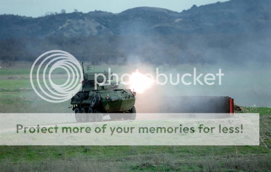
Image

Therefore, I used some of my stock grasses, from 2 different suppliers: the majority came from the excellent MiniNatur (SilFlor) range from the Antenocitis Workshop company:

Image

Image

Comes in different colours and sizes, but, importantly, it is self-adhesive. Though, in this case, I maximised the glue by using thinned PVA in a tub. That's right. Each individual clump of grass was stuck down and then assessed as a whole; does it look right? Does it look too much or too little? You know when to stop when you think it looks too much - you'll always be about right then..

Image

The other type, just for variation was from a company called Green Line Scenics, from Reality in Scale. These were loose, in a pack of 50 and again, I used PVA to glue them down to the powdery surfaces. This was a time-consuming process; taking up about 3 hours of placing, assessing and re-positioning.

The final aspect to take care of were the stains and weathering marks on the Jersey Blocks. Although the Steel I-beam has primer paint on it, it is reasonable to assume that sometimes it gets scratched. Rust is an inevitability of this process, as is mud and dirt from passing vehicles. I used the excellent Flory Models Rust powder and the Pinnacle Light Mud Powder along the Jersey block joins, very sparingly at points along the beam and particularly between the Jersey blocks, where water has a natural run-off:

Image

Image

Image

Image

Image

Overall, the effect is quite pleasing. Less is more, so they say and this is a case in favour of that point. I added a few clumps of grass where it might naturally grow - by joins and various spots along the Jersey blocks.

With the base finally completed, I had somewhere for the vehicle to go, which was important for the next phase, completing the vehicle itself and the all-important firing gun. This was the part of the project I wasn't looking-forward to and forced me to totally rethink what it was I was after in the effect.


The Firing Gun Effect

I work with electronic components and circuits all of the time; at the University where I teach and instruct in many aspects of technology, product design and systems. I see this problem every time a student comes to me and asks if such a thing is possible and, more often than not, we do manage to work through the problem to a successful conclusion.

This time, it was my own project I was working through and I had all sorts of ideas about how to illuminate a 5V wide-angle, bright-white LED. Essentially, the components for this project are just two batteries and an LED:

Image

Two of these CR2032, 3V low-profile lithium batteries, placed in series, giving me 6V and:

Image

Image

One of these 140 degree wide-angle, 5V Bright-White LED's. These are robust LED's and although the required input is 5V, the bulbs are not adversely affected by the 6V we were running. I really didn't bother with a resistor - just adds to the terminal connections and the 'package size'.

One thing I did know - once the package was all connected up, it was not coming out. Once on, the LED stays on until the batteries die. I calculated that with the batteries able to provide around 225mA/hr (450mA/hr total) of power and the LED drawing around 25mA, I'd have around 24 hours of continuous use. In reality, the amount of power drawn was less and the LED was still going strong more than 72 hours later. Better get those final photos in before the whole effect dies off...

Now connecting the LED was more problematic. The longer pin, being the Anode (positive voltage) could sit on the top surface of the batteries. The short pin, the Ground (zero volts, sometimes erroneously called negative) had to go right underneath the batteries, which meant running it to the back without it touching the positive areas of the batteries. The solution was to just isolate the edges using electrical tape and then using the tape to stick down the pins of the LED to the respective surfaces:

Image

The advantage of using the round CR batteries was that their shape was also the perfect base for the surrounding Polyester wadding.

Image

The problem now was, how to get the wadding to conform around the batteries. The answer was actually very simple - use a clear Varnish - in this case Alclad Klear Kote Matte (ALC-313) and use the tackiness of the airbrushed coating to form the surrounding flash ball and to adhere it to the batteries without causing a short - something many glues, including CA types can do (as well as eat away the polyester)

Image

After lacquer airbrushing a reasonable amount of wadding in my hand, I left it for a minute to allow the coat to harden very slightly. Then, I was able to form it into a rough cone shape and the hardening lacquer varnish holds the wadding fibres together. To get the wadding onto the lit LED, I poked a 'hole' into the wadding that covered the batteries and folded the wadding over - a bit like a glove. It was then a case of reshaping and forming. This took around 20 minutes before I was happy with the overall effect and the shape looked about right.

Once formed, I left the wadding to completely dry. By continuing to handle the wadding as it cures, it sticks to your hands and works against the effect you're after by pulling at fibres. I left the whole thing overnight.

With the Klear Kote dry and the rough cone formed over the brightly-lit lED, it was then a case of adding a support which would connect the lit wadding to the gun. By chance, I happened to be looking for clear tubing and finding none, when I noticed the thin, clear plastic tubes covering brush heads.

Image

Finding several which covered the gun tightly but not overly-so, I shorted the length to around 15mm and, using CA glue, glued the end of the tube onto the back of the battery pack. The wadding surrounded the tube, masking it. I left the whole thing to fully cure for around 30mins. Before adding it to the gun, I needed to add some of the distinctive yellow flash. In the end, nothing simpler than GS H91 Clear Yellow:

Image

I thinned this to around 70:30 tinnners/paint and 15psi low pressure, I airbrushed it over the wadding starting at the widest part of the cone and working carefully around until the effect was as I wanted. The point to stop is when it starts to dry and you see the light dimming slightly - so it is best to do a thin layer, let it dry, assess the effect and, if necessary continue. This took me around an hour of pausing and assessing until it looked ok.

Now, the moment of truth, fitting the clear sleeving tube over the gun. I had to be very, very careful here - one ham-fisted shove and it could all go wrong at the last. However, in this case, things went smoothly and the tubing fit tightly over the gun, supporting the wadding, 2 batteries and an LED (plus the weight of the paint and lacquer varnish). Since the gun had been glued into the elevated position, the whole effect looked tremendous - especially in low light.

So, now that the major aspects of the build had been completed, it was time for the details. As I mentioned, I was using the Black Dog LAV-R set, which came in very useful; adding enough components to the vehicle without them being 'inappropriate' to the overall scene. They'd been painted and weathered with light dustings of the Pinnacle Might Mud, as was the rest of the vehicle - particularly the underside, even though much would not be seen.

The components were placed around the vehicle in places where you would think they'd be found; tyre at the front, along with the waterproofed cabling, rather than hung from a side or by exhausts or near the turret. I usually just add squares of double-sided tape which has the added advantage of not gluing the components to the vehicle, allowing me to remove them later for dusting or upgrades.

So, I ran through my checklist once more - which is good because I'd forgotten one thing - expended round shell casings from the mighty GAU-12 during firing. The gun was firing but where were the shells? Ok, another challenge, but one I knew I could finish. I looked about for pictures of the gun firing and they all seemed to show the trajectories to be about the same - just in different angles. Working on this premise, I decided to leep it very simple. I found a thin piece of stainless wire and formed a roughly ballistic shape. Painting it with the Vallejo Polyurethane Primer gave it a hard casing for the shells to be stuck onto. Rummaging through my stock of Albion Alloys, I found some 0.9mm tubing, which approximates the 25mm shell casing of each 25mm by 137mm round:

Image

Cutting the brass rod into lengths of approximately 4mm+/- until I had around 75 rounds in total. 25 of these expended rounds would be in-flight, expending from the gun in a rough arc, while the remaineder would be scattered randomly on the dusty floor in a loose pile. Gluing the shells to the black wire was a simple matter of dunking the shell in a blob of rapid CA (5 second), with a pair of tweezers and sticking it to the wire. Creating the random pattern for each round was just a question of changing angle and orientation, both ABOVE and BELOW the wire:

Image

Image

The effect was both quick and effective and the result was very pleasing indeed. I may well use this technique again!

A couple of URL's show the amazing GAU-12 in operation, both during the day and at night:

http://youtu.be/XooFmPUt6aA - a daylight video of the LAV-AD in a promotional video

https://www.youtube.com/watch?v=EM82Vuq3PdM - a night-firing exercise in Iraq. Just listen to the noise of that gun in action!

So, another hurdle completed and, by now, I was reinvigorated into completing this project. If I made the deadline of January 9th, then that would be a bonus - but none of this would mean much if I didn't complete these notes for others to see my process and think it might be something they'd like to try - which means a lot to someone who teaches others for a living.

Essentially, only one aspect of the build remained - the test range flags. Vehicles on a test range always carry Green and Red coloured flags, to indicate whether their weapon systems are armed or whether they are 'safed' during transit:

Image

As you can see in this photo, the Red flag is prominently fitted to the vehicle, indicating a live weapon system. Although not visible in this photo, there would have been a green flag either within on or the vehicle for change-over with the 'safed' weapon systems.

For the LAV-AD, I wanted to add both flags, one raised, one stowed. Again, I decided to keep things simple. A couple of cocktail sticks, with the mid-section trimmed away, provided both poles for the flags and, although they did look a little large, they were to hand - given the short time I had for the submission of this build:

Image

The flag material was easy for the Green flag - I just used my light Green tape and cut out a section measuring around 25mm by 15mm then hooked it around the pole, trimming the excess until it looked even:

Image

Image

The Red flag was a little more work, simply painted a section of fine masking tape using Tamiya XF-2 Flat White as the base, followed by a coat of GS H13 Flat Red, lightly sprayed over the top. I was thinking of adding some Orange - just to make the flag brighter - but decided against it in the end:

Image

I put the Red flag by the rear tail light cage, which held it quite naturally and wouldn't have obstructed the rear doors opening in the real world:

Image


And with that, my friends, the build is now complete. The checklist is thoroughly completed and nothing seems to be amiss. It was a little rushed, in the end, but I think this stands as one of the finest armoured vehicles I have done. I have learned an awful lot from others in making this build - the most important of which is doing a build subject which you are going to do without rushing! Perhaps, next time, things will be different. Ah, hindsight. The final build photos will be uploaded once they have been edited. Thank you for watching and your time.